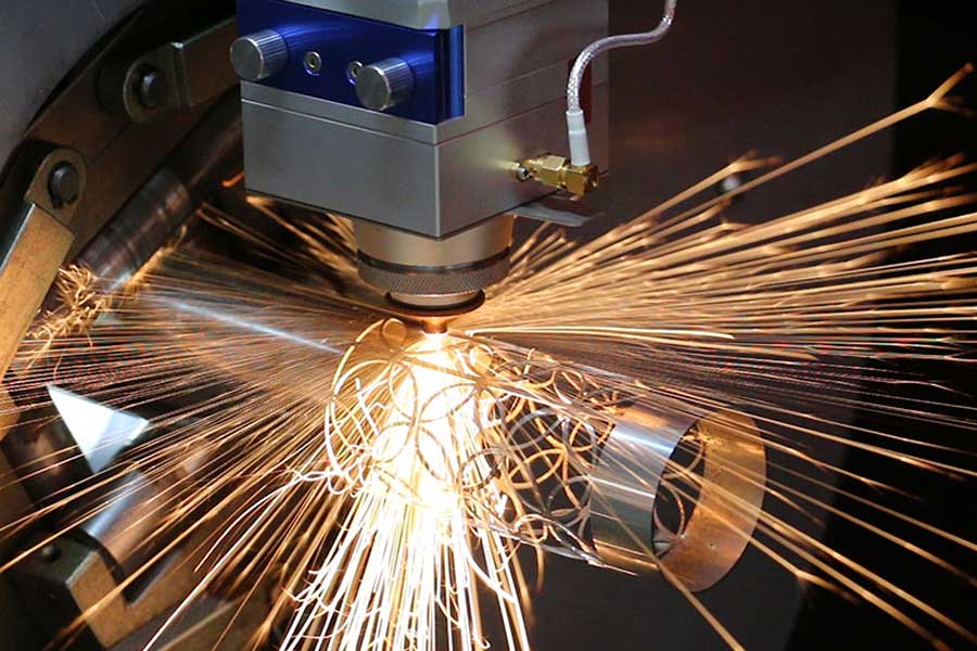
When specifying cutting infrastructure for seamless carbon steel line pipe in API 5L grades X42 through X70, the transition from traditional sawing or plasma beveling to a heavy duty tube laser for seamless carbon steel line pipe is rarely about raw speed. It is about eliminating the secondary machining operations that plague high-volume structural fabrication. In my experience commissioning these systems across certified fabrication shops, the decisive factor is not the kilowatt rating of the resonator but the rigidity of the material handling system and the predictability of the cut face under variable pipe straightness tolerances.
Let me be direct: a seamless pipe, by nature, carries a +1% / -0.5% wall thickness tolerance and a residual stress profile that causes micro-ovality. A standard light-duty laser carriage will fight this. The machine must be engineered with a high-inertia gantry and a self-centering chuck system capable of exerting a radial clamping force of 2.5 to 3.0 MPa without inducing deformation on the pipe end. If you are cutting S355JR or higher-strength micro-alloyed steels (e.g., X65 with a yield strength of 450 MPa), the cut head must maintain a focal point position accuracy of ±0.05 mm against the pipe’s surface variance. This demands a capacitive height sensor with a dynamic response frequency above 5 kHz, not the 1 kHz units found on sheet metal machines.
Metallurgical Integrity and Process Gas Dynamics
The primary failure mode in laser cutting of line pipe is not slag adherence; it is nitride precipitation on the cut edge. For structural applications requiring subsequent welding, you cannot tolerate a nitrogen-rich layer. This is why we run the cutting process with a pure oxygen stream for the piercing phase at a delivery pressure of 1.2 MPa, then switch to a high-purity nitrogen (99.998%) assist gas for the final severance at 1.5 MPa. This dual-gas strategy prevents the exothermic reaction from running away on the underside of the pipe, which would otherwise create a hard, brittle oxide that fails Charpy impact tests.
For a 6-meter length of 8-inch Schedule 40 seamless pipe, the thermal load is substantial. The laser source—typically a 6 kW to 8 kW fiber laser operating at a wavelength of 1070 nm—must be pulsed at a duty cycle not exceeding 70% during the cutting of the circumference. Running at 100% duty cycle on a rotating pipe causes heat accumulation at the 9 o’clock position, leading to a phenomenon we call “droop cutting.” The kerf width widens from the nominal 0.3 mm to 0.8 mm, and you lose the squareness of the edge required for EN 1090 Class 2 execution.
Comparative Analysis: Legacy vs. Laser Processing
To quantify the operational shift, consider the following data compiled from a recent line pipe skid fabrication facility upgrade. The comparison is based on cutting a 219.1 mm OD x 12.7 mm wall, X52 grade pipe, with a 30-degree bevel requirement for full-penetration welds.
| Parameter | Conventional Plasma (HD) + Machining | Mechanical Sawing + Lathe Beveling | Heavy Duty Tube Laser (8kW) |
|---|---|---|---|
| Kerf Width (mm) | 4.5 – 6.0 | 3.0 – 4.0 (Blade thickness) | 0.8 – 1.2 |
| Heat Affected Zone (HAZ) Depth (mm) | 1.5 – 2.5 | 0.5 (Work hardening) | 0.2 – 0.4 |
| Bevel Angle Accuracy (Degrees) | ±2.5 (Requires separate torch angle) | ±1.0 (Mechanical tolerance) | ±0.5 (Programmable 3D interpolation) |
| Surface Roughness (Ra, µm) | 12.5 – 25 (Dross present) | 6.3 | 3.2 – 6.3 |
| Secondary Operations Required | Grinding, slag removal, separate beveling | Deburring, chip removal, tool wear compensation | None (Direct to fit-up) |
| Cycle Time per Cut (incl. index) | 4 min 15 sec | 6 min 40 sec | 2 min 05 sec |
| Edge Hardness Increase (HV) | +80 to +120 HV | +30 to +50 HV (Cold work) | +10 to +15 HV |
Notice the HAZ depth. In a plasma cut, that 2.5 mm brittle layer must be physically removed before welding to prevent hydrogen cracking. The laser’s narrow HAZ allows you to weld directly on the cut edge, provided the nitrogen purge is active. This is where the EN 1090 compliance argument solidifies. The standard mandates that cutting processes must not adversely affect the base material properties. With laser, the reduction in toughness is negligible, whereas plasma often requires a full 3 mm of material to be machined away from the weld prep area to restore ductility.
Chuck Design and Seamless Pipe Ovality Compensation
Let us discuss the mechanical interface—the chuck. A seamless pipe is not perfectly round. It has a tolerance of 1% of the nominal OD. For a 323.8 mm pipe, that is a 3.2 mm deviation. If your chuck jaws are rigid, you will clamp the pipe into a circular shape, but the laser head will follow the mandrel axis, not the pipe surface. This creates a variable focal point distance.
The correct approach, which I have implemented on several projects, involves a three-jaw chuck with a pneumatic cushioning circuit. The clamping pressure must be regulated to 2.8 MPa for the initial grip, then reduced to 1.8 MPa during rotation. This allows the jaws to “float” slightly, following the natural ovality of the pipe. Simultaneously, the laser head’s capacitive sensor reads the surface distance 10,000 times per second, adjusting the Z-axis to maintain the focal point. If you skip this floating chuck design, you will experience catastrophic focus errors on every rotation, resulting in a spiral cut line on the pipe surface.
Certification Readiness and Documentation
Moving toward the certification aspect, the software suite is as critical as the cutting head. For EN 1090 compliance, you need full traceability. The machine control system must log the exact laser power, feed rate, gas pressure, and date/time stamp for every single cut piece. This data must be exportable in a non-editable format (e.g., CSV with checksums) to satisfy the factory production control (FPC) audit. I insist on specifying a system that integrates directly with the welding procedure specification (WPS). If the WPS calls for a specific bevel angle, the laser program must lock that parameter to prevent operator override.
Furthermore, the machine must be capable of producing a “cut quality report” per batch. This report should include the measured surface roughness and the absence of notches. In a recent audit for a client supplying to the Dutch offshore sector, the auditor specifically requested the laser’s pierce log to verify that the pierce point was located on the scrap end of the pipe, not within the finished length. This level of detail is only achievable with a modern CNC laser, not with manual sawing.
Finally, consider the floor space logistics. A laser tube cutting cell with an automated loading magazine for 12-meter pipes requires a footprint of roughly 20 meters by 5 meters. This is comparable to a large sawing station but eliminates the need for a separate deburring bench and a chip conveyor system. The reduction in indirect labor is substantial—typically one operator can manage two laser cells, whereas plasma cutting requires one operator per station plus a dedicated grinder.
In terms of operational expenditure, the shift from consumable electrodes and saw blades to laser optics and gases yields a cost per cut reduction of approximately 30-40%, primarily driven by the elimination of tool wear and the reduction in material waste (kerf loss). For a facility processing 500 tons of seamless pipe annually, this translates to a payback period of under 18 months, even with the higher initial capital expenditure.
Frequently Asked Questions for Procurement Engineers
Q1: What is the minimum wall thickness that a heavy-duty tube laser can process on seamless carbon steel line pipe without compromising the cut speed or edge quality?
For seamless pipe, the practical minimum wall thickness is 4.0 mm for reliable piercing and cutting. Below this, the pipe tends to act as a heat sink inconsistently due to the manufacturing tolerances of seamless rolling. For walls between 4.0 mm and 6.0 mm, we typically reduce the oxygen pressure to 0.8 MPa to prevent excessive burning on the exit side. For walls above 25 mm, you will need to consider a 12 kW resonator and a slower feed rate to maintain a striation-free cut.
Q2: How does the laser cutting process affect the end face perpendicularity required for API 5L line pipe joining?
Laser cutting achieves a perpendicularity tolerance of ±0.1 mm across the pipe diameter, which is superior to the ±0.5 mm typically achieved with a saw. However, the critical factor is the synchronization between the rotary axis (chuck rotation) and the linear axis (cut head movement). The CNC controller must use a high-resolution encoder on the chuck—at least 0.001 degrees—to prevent a helical cut path. This is a standard feature on heavy-duty machines but is often absent on converted sheet metal lasers.
Q3: What specific maintenance protocols are required for the optical path when cutting high-sulfur content seamless pipe (e.g., API 5L X42 with high MnS inclusions)?
High-sulfur steels produce a fine iron sulfide dust during cutting. This dust is abrasive and conductive. You must install a positive pressure air purge on the cutting head (5 psi clean dry air) to prevent particulate ingress into the focus lens housing. Additionally, the protective window (cover slide) should be inspected every 8 hours of operation. In contrast to clean structural steel, you will likely replace the cover slide every 40 hours instead of every 200 hours. Failure to do so will result in a gradual power loss and a degraded cut edge that fails visual inspection.













