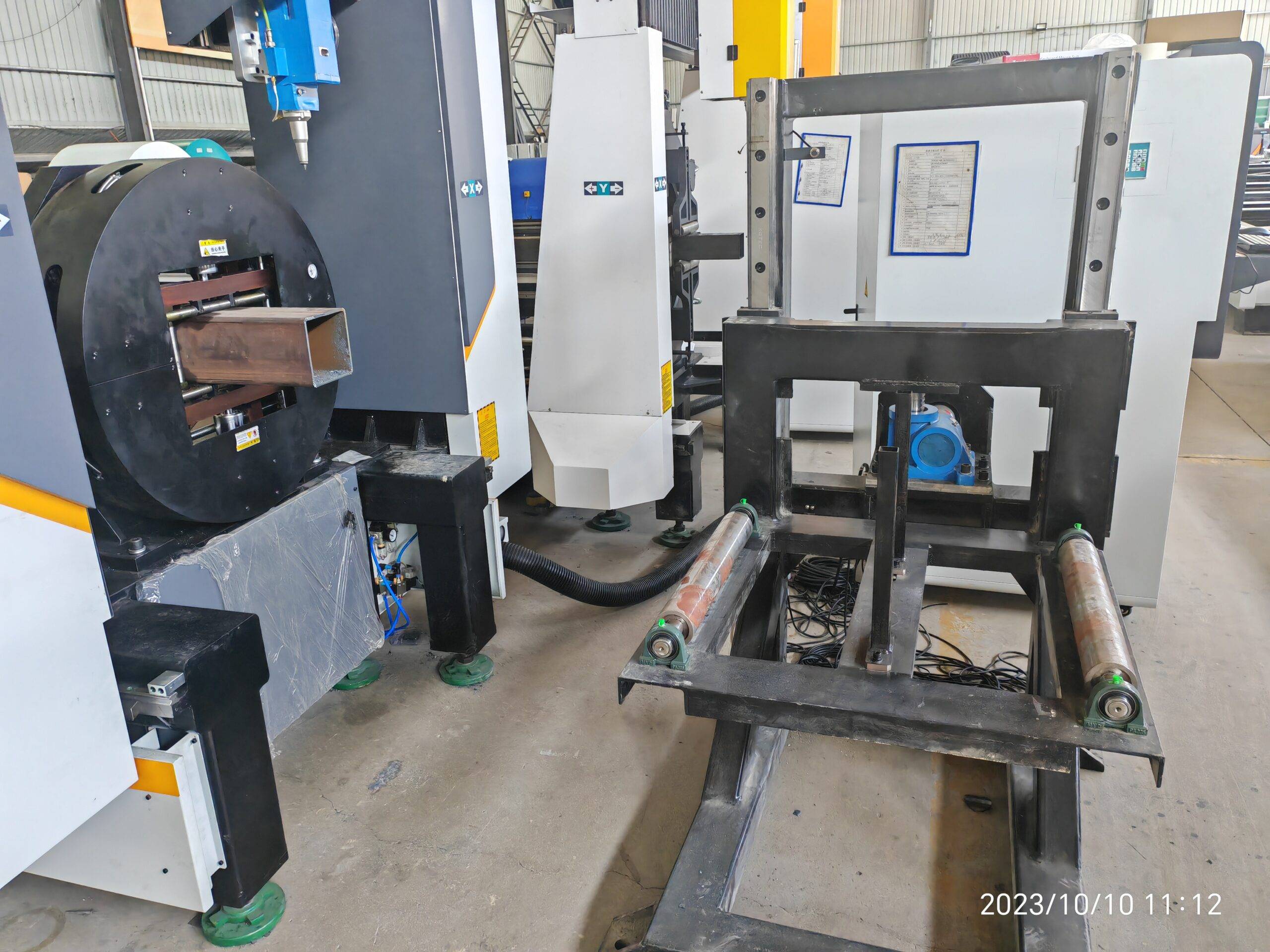
Processing Efficiency, Dynamic Speed Benchmarks, Structural Beveling and Root Gap Tolerances
Fiber laser tube processing has fundamentally rewritten the manufacturability envelope for structural brackets in airframe assemblies and body-in-white (BIW) chassis nodes. The core engineering driver is not simply cut quality; it is the ability to hold tolerances of tube laser cutting in aerospace and automotive brackets across variable wall thicknesses, ovality, and alloy-specific thermal responses. On the shop floor, this translates to a hard conflict: the same 3 kW–6 kW source that pierces 4 mm S355JR at 1.2 MPa nitrogen must also hold ±0.05 mm on a 1.5 mm SUS304 hydraulic return line bracket without dross adhesion. That duality defines the modern tube laser cell.
Alloy-Specific Thermal Behavior and Parameter Windows
Bracket families split into three metallurgical camps, each demanding distinct frequency and duty cycle profiles.
- S355JR / S420MC structural brackets: Oxygen-assisted cutting at 0.8–1.0 MPa delivers the exothermic boost needed for 6–10 mm wall sections. Frequency is typically locked at 5 kHz continuous wave (CW) for straight contours, switching to 2 kHz gated at 60–70% duty cycle on tight radii to prevent edge rounding. Kerf width stabilizes at 0.35–0.45 mm.
- SUS304 / 316L fluid and sensor brackets: High-pressure nitrogen at 1.4–1.5 MPa, 1.5–2.0 mm nozzle standoff, 8–12 kHz modulated. The austenitic matrix work-hardens at the cut edge; uncontrolled heat input pushes HAZ past 80 µm and initiates intergranular sensitization in 316L. Duty cycle is capped near 55% on thin walls to control dross.
- Al6061-T6 and 7075 aerospace brackets: Nitrogen at 1.2–1.4 MPa, 4–6 kHz, with pierce times extended 30–40% versus steel to avoid spatter-induced lens contamination. Reflectivity at 1064 nm demands anti-reflective optics and pierce power ramping.
Chuck pneumatic pressure is the silent variable. Rotary chucks clamping thin-wall Al6061 tube above 0.6 MPa induce ovality that propagates directly into the cut plane, producing out-of-roundness exceeding 0.1 mm on a nominal 40 mm OD tube. Field practice: 0.4–0.5 MPa on aluminum, 0.7–0.9 MPa on steel, with servo-synchronized chuck rotation to eliminate slip during high-G contouring.
Dynamic Speed Benchmarks and Efficiency Modeling
Throughput on a tube laser is governed by acceleration, not peak velocity. A modern 3D tube cell with 1.5 G axis acceleration and 120 m/min rapid traverse loses 18–25% of theoretical cycle time to corner deceleration on bracket geometries with dense hole patterns. Real benchmarks for a 2.5 mm S355JR bracket with 14 holes and two 45° beveled ends:
- Cut length: 1,850 mm
- Effective cutting speed: 4.2 m/min average (peak 9 m/min on straights)
- Pierce count: 16 (0.35 s each on 2.5 mm)
- Net cycle: 38–42 s per part, chuck-to-chuck
Compare that to a 6 mm Al6061 bracket: speed drops to 2.8 m/min average, pierce time rises to 0.9 s, and cycle time nearly doubles. The efficiency lever is nesting density and common-line cutting, which can reclaim 12–15% of material and 8% of cycle time on bracket families sharing hole patterns.
Structural Beveling and Root Gap Tolerances
Beveled tube ends for welded bracket joints are where tolerance stack-up becomes brutal. A 45° bevel on a 3 mm S355JR wall must hold land thickness of 1.0 ±0.15 mm and bevel angle within ±1.5°. Exceed the land tolerance and the weld root gap opens beyond the 0.5–1.5 mm window required for consistent GMAW penetration. The laser head’s Z-axis following accuracy (±0.03 mm) and the tube’s own straightness (typically 0.5 mm/m for seamless, 1.0 mm/m for welded tube) directly consume the tolerance budget.
Root gap control on aerospace brackets is tighter: 0.2–0.8 mm for autogenous laser welding of 1.5 mm SUS304. Here, cut edge perpendicularity must stay within 0.05 mm over the wall thickness, which mandates nitrogen cutting, focal position held at −0.5 mm below surface, and a nozzle in good condition. A worn nozzle of 0.1 mm oversize shifts kerf taper enough to blow the root gap tolerance.
Comparative Technical Data: Legacy vs. Fiber Laser Tube Cutting
| Parameter | Plasma / Mechanical Saw (Legacy) | Fiber Laser Tube Cutting |
|---|---|---|
| Dimensional tolerance (typical) | ±0.5 to ±1.0 mm | ±0.05 to ±0.15 mm |
| Bevel capability | Manual secondary op, ±3° | In-process 3D bevel, ±1.5° |
| HAZ width (SUS304, 2 mm) | 200–400 µm | 40–80 µm |
| Dross / secondary cleanup | Grinding required | Minimal to none with N₂ |
| Cycle time (2.5 mm S355JR bracket) | 90–140 s (multi-op) | 38–42 s (single op) |
| Root gap consistency for welding | Poor, ±0.6 mm variance | Controlled, ±0.1 mm variance |
| Assist gas | Compressed air / O₂ | N₂ 1.2–1.5 MPa / O₂ 0.8–1.0 MPa |
Field Diagnostics: Where Tolerances Actually Fail
In 20 years of commissioning tube cells, the tolerance failures I see trace back to four root causes, in order of frequency: chuck pressure drift on thin-wall aluminum, nozzle wear on nitrogen cuts, thermal drift of the linear axis after 4+ hours of continuous duty, and inconsistent tube incoming straightness. The first two are operator-controllable. The third requires active thermal compensation or a 30-minute warm-up cycle before first-article inspection. The fourth is a supply chain problem that no machine setting can fully absorb—if incoming tube ovality exceeds 0.8% of OD, no laser parameter set will hold ±0.05 mm on the cut plane.
For aerospace brackets, add a fifth: fixture-induced distortion during multi-axis indexing. A 4-jaw chuck rotating a 60 mm Al7075 tube through 180° of contouring will introduce torsional wind-up if the chuck synchronization lags by more than 0.02°. The fix is servo tuning, not parameter tweaking.
Procurement FAQ
What tolerance can a fiber laser tube cutter realistically hold on 2 mm SUS304 brackets?
±0.05 mm on cut length and hole position, with edge perpendicularity within 0.05 mm over the wall thickness, provided nitrogen assist gas is maintained at 1.4–1.5 MPa and the nozzle is within specification. Tighter than ±0.03 mm requires climate control and active thermal compensation.
How does chuck pneumatic pressure affect bracket roundness and cut tolerance?
Excessive clamping pressure deforms thin-wall tube before the beam ever fires. On Al6061 tube under 3 mm wall, keep chuck pressure at 0.4–0.5 MPa; on steel, 0.7–0.9 MPa. Above these values, ovality propagates into the cut plane and root gap tolerances for downstream welding are lost.
Can a single tube laser cell handle both S355JR chassis brackets and Al7075 aerospace brackets?
Yes, but not without parameter set changes and nozzle/gas swaps. The metallurgical windows are incompatible: S355JR runs oxygen at 0.8–1.0 MPa with CW or low-frequency gating, while Al7075 requires nitrogen at 1.2–1.4 MPa with extended pierce ramping. Budget 15–25 minutes for a validated changeover including first-article verification.













