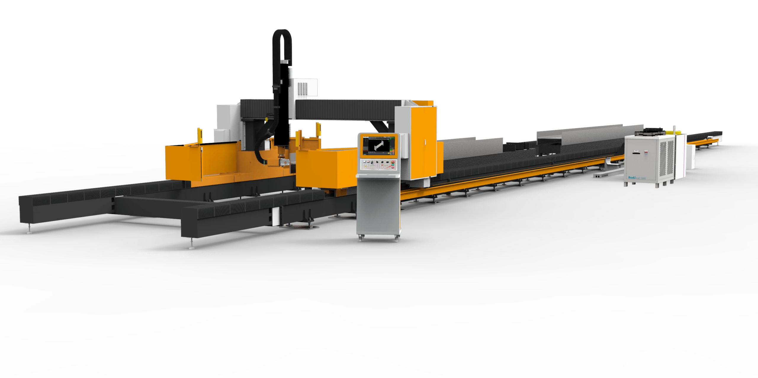
The transition from batch-processed, cut-and-weld torque tube fabrication to continuous, in-line laser processing is not a matter of convenience; it is a fundamental re-engineering of the production line’s physics. When we discuss a solar tracker torque tube automatic laser cutting machine, we are specifically addressing the elimination of secondary operations, the reduction of thermal distortion, and the synchronization of cutting speed with structural welding tolerances. In my experience commissioning these systems for utility-scale PV plants, the primary failure point is not the laser source itself, but the mechanical handling of the 6- to 12-meter-long, often torsionally flexible, S355JR or S420MC tubes. The machine’s ability to maintain a consistent focal point position while the tube rotates and translates is the true benchmark of engineering viability.
Processing Efficiency: The Mechanical Constraint Hierarchy
Efficiency in this niche is governed by the Law of Conservation of Angular Momentum applied to a hollow section. The cutting head might be capable of 20 kW of power, but if the chucking system cannot accelerate a 10-meter, 3mm-wall tube to a rotational speed that matches the feed rate, you are creating a bottleneck. We typically operate with a dual-chuck, servo-driven system where the tailstock and headstock are synchronized to within ±0.01 degrees of rotational error. The pneumatic clamping pressure is critical; for a 200mm x 200mm square tube, we set the chuck gripping force to 4.2 MPa, but for a 300mm diameter round tube, we must reduce this to 3.5 MPa to prevent ovalization at the bearing points. The processing efficiency is not measured in meters per minute, but in “parts per hour” against a specific hole pattern—typically 40 to 60 holes per tube for mounting brackets. Here, the laser’s piercing time (0.2 seconds for a 12mm hole in 3mm S355JR) is negligible compared to the axis repositioning time, which is why we specify a maximum axis acceleration of 1.5 G on the longitudinal feed.
Dynamic Speed Benchmarks and Inertia Compensation
Let us establish a concrete benchmark. On a standard 3kW solid-state laser (wavelength 1070nm), cutting a 4mm wall Al6061-T6 torque tube, we achieve a cutting speed of 4.5 meters per minute with a Nitrogen assist gas delivery pressure of 1.5 MPa. However, the dynamic challenge arises during the transition from a longitudinal cut to a circumferential cut at the tube’s end. The rotational axis (A-axis) must decelerate from 120 RPM to zero, and the Y-axis must simultaneously accelerate to maintain a constant tangential velocity at the cutting nozzle. If the servo tuning is not optimized with a high-speed EtherCAT bus (cycle time < 1ms), you will observe a "dwell mark" at the corner. This is unacceptable for structural integrity. In contrast, for SUS304 stainless steel torque tubes (often specified for coastal corrosion resistance), we reduce the Nitrogen pressure to 1.2 MPa to prevent edge oxidation and maintain a dross-free cut, but we must increase the piercing duty cycle to 15% to avoid thermal buildup in the corner radii.
Structural Beveling and Root Gap Tolerances
The most contentious issue on the workshop floor is the preparation of the weld bevel. For a torque tube that is to be butt-welded to a stub axle, the laser must produce a bevel angle of 30° ± 1° on the top edge and 25° ± 1° on the bottom edge (a “K” profile). This is achieved not by tilting the head, but by manipulating the beam vector via the CNC kinematics. The critical parameter here is the root face height; we must maintain a root face of 1.5mm ± 0.2mm. If the laser cuts too deep, the root gap opens up beyond 2.0mm, causing burn-through during the subsequent MIG welding process. We utilize a capacitive height sensor with a sampling rate of 10 kHz to map the tube’s surface. However, the real issue is the “barrel effect” on the tube’s cross-section. If the tube has an ovality of more than 0.5% (which is common in rolled S355JR), the focus position shifts by 0.15mm, which is enough to alter the bevel angle by 2 degrees. To counter this, we implement a dynamic focus control system that adjusts the Z-axis in real-time based on a pre-scanned map of the tube’s circumference, ensuring the root gap tolerance is held even on non-ideal raw material.
Comparative Analysis: Conventional vs. Laser Integration
To quantify the operational advantage, we must compare the laser process against the legacy method of plasma cutting followed by a separate chamfering mill. The data below is derived from a recent line audit for a 500MW solar tracker project, processing 4-meter long, 200x100x4mm rectangular tubes.
| Parameter (Per 4m Tube) | Conventional Plasma + Mechanical Chamfer | Automatic Fiber Laser (3kW) |
|---|---|---|
| Cycle Time (40 holes + 2 bevel ends) | 14 minutes 30 seconds | 6 minutes 10 seconds |
| Thermal Distortion (Longitudinal bow) | 2.5 mm / meter (requires straightening) | 0.3 mm / meter (no post-processing) |
| Kerf Width (Cutting tolerance) | ± 0.8 mm (plasma arc instability) | ± 0.1 mm (consistent beam diameter) |
| Bevel Angle Consistency | ± 3° (mechanical cutter wear) | ± 0.5° (laser parameter stability) |
| Secondary Operations | Deburring, slag removal, separate chamfering | None (cut and bevel in same pass) |
| Assist Gas Consumption (per tube) | N/A (dry cutting) | 0.8 m³ Nitrogen @ 1.4 MPa |
| Tooling Wear Cost | High (carbide inserts replaced every 200 tubes) | Negligible (no physical tool contact) |
The data clearly indicates that the laser solution does not merely improve speed; it collapses the process chain. The elimination of the mechanical chamfering station alone reduces the floor space requirement by 18% and removes a potential safety hazard regarding rotating cutter heads.
Metallurgical Integrity and Gas Dynamics
We must also discuss the metallurgical impact on the cut edge. When cutting S420MC (a micro-alloyed steel used for high-strength torque tubes), the heat-affected zone (HAZ) must be minimized to prevent hardening at the edge, which can lead to cracking during the cold-forming of the tube end. Using a 6kW laser with an Oxygen assist gas at 1.2 MPa, we achieve a cutting speed of 8 m/min, but the exothermic reaction of Oxygen with iron creates a thin oxide layer. For welding, this oxide must be removed. Therefore, for high-integrity welds, we switch to Nitrogen at 1.5 MPa, which reduces the speed to 5.5 m/min but yields a clean, oxide-free edge. The decision matrix is simple: if the tube is to be welded immediately, use Nitrogen; if it is for a bolted connection, Oxygen is acceptable for the cost savings. The laser’s pulsing frequency also plays a role; a continuous wave (CW) beam is used for thick sections, but for thin walls (2mm), we utilize a pulsed beam at 500 Hz with a 30% duty cycle to reduce the average heat input and prevent warping of the flange area.
FAQ: Industrial Procurement Considerations
Q1: What is the realistic payback period when switching from plasma cutting to a laser system specifically for torque tubes, considering the higher initial capital expenditure?
The payback is driven by labor reduction and consumables. A plasma system requires a dedicated operator for the cutting table and another for the chamfering mill. The laser system, with automated loading and unloading, can be supervised by a single operator managing two machines. Additionally, the cost of plasma electrodes, nozzles, and shield caps is roughly $4.50 per hour of operation, whereas laser optics (protective windows) cost approximately $1.20 per hour. Factoring in the elimination of the straightening press (which costs $60/hour in energy and labor), most of our clients see a capital payback in 2.8 to 3.5 years, assuming a single-shift operation. This drops to 1.8 years on a two-shift basis.
Q2: How does the machine handle the varying lengths and diameters required for different tracker designs (e.g., single-axis vs. dual-axis) without extensive changeover time?
Modern systems utilize a “soft-tooling” approach. The chuck jaws are segmented and can be adjusted via servo motors to accommodate a diameter range from 80mm to 300mm without manual intervention. The changeover is managed by the CNC program, which recalls the specific chuck pressure (calculated based on wall thickness to prevent deformation) and the longitudinal support positions. The critical factor is the automatic measurement of the tube’s actual length upon loading; a laser distance sensor measures the tube end and adjusts the cutting program origin automatically. This reduces the changeover time between different profiles to under 90 seconds, which is essential for just-in-time manufacturing.
Q3: What are the specific maintenance requirements for the optical path and the debris extraction system when cutting galvanized or pre-painted torque tubes?
Cutting galvanized steel (Z275 coating) releases zinc vapors that can condense on the protective lens. We mandate a “cross-flow” cutting head design where a high-velocity air knife (0.8 MPa) creates a barrier between the nozzle and the lens. The filtration system must be a cartridge-type collector with a spark arrestor, specifically rated for L-class dust (explosive). The filter media must be changed every 500 hours of operation when cutting galvanized material, compared to 1000 hours for bare steel. Furthermore, the fumes are heavier than air; the machine’s enclosure must have a downdraft table design with a face velocity of 0.5 m/s to ensure worker safety and compliance with OSHA silica and metal fume exposure limits.













