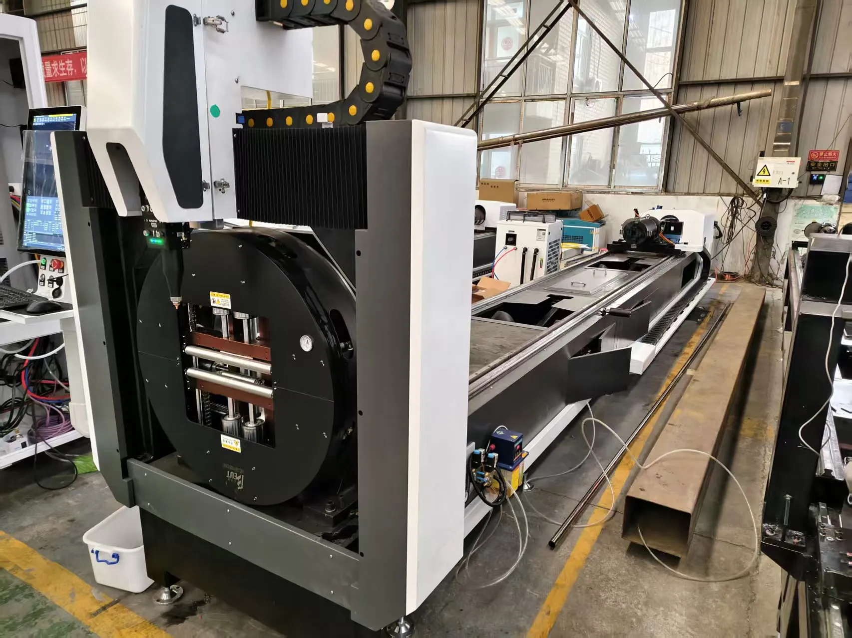
Processing Efficiency, Dynamic Speed Benchmarks, Structural Beveling and Root Gap Tolerances in Heavy-Wall Tubular Fabrication
When a fabrication shop moves from 12 mm wall tubing into 25 mm, 32 mm, or 40 mm structural pipe, the cutting process stops being a “profile” problem and becomes a thermal mass problem. The decision matrix between laser cutting vs plasma for thick wall structural steel pipes is not a marketing question — it is a question of heat input per unit length, kerf geometry control, and whether your downstream welding cell can tolerate a 1.5 mm root gap variance. On the floor, the answer usually splits by wall thickness band, alloy, and whether the joint requires a beveled land.
Thermal Physics: Why Thick Wall Changes Everything
Plasma cutting operates on a constricted arc at roughly 25,000–30,000 K, transferring energy through a high-velocity ionized gas jet. On a 25 mm S355JR pipe wall, a 200 A plasma torch running at 1.4 MPa oxygen or air produces a kerf of 3.0–4.5 mm with a top-edge rounding radius of 0.8–1.2 mm and a bevel angle of 3–7 degrees on the cut face. That is acceptable for a fillet weld on a handrail. It is not acceptable for a full-penetration butt joint on a 32 mm pressure pipe where the WPS calls for a 2.0 mm ± 0.5 mm root gap.
Fiber laser cutting at 6 kW to 12 kW on the same 25 mm wall behaves differently. The 1070 nm wavelength is absorbed far more efficiently by ferrous alloys than the CO2 legacy systems, and the focused spot (typically 0.15–0.30 mm with a 200 mm collimator and 125 mm focusing lens) delivers power density in the 10^7 W/cm² range. Kerf on 25 mm carbon steel with nitrogen assist at 1.5 MPa sits at 0.8–1.2 mm. The cut face perpendicularity is typically within 0.5 degrees, and the heat-affected zone is 0.1–0.3 mm versus 0.8–1.5 mm for plasma. That HAZ delta matters on quenched-and-tempered grades and on SUS304 where sensitization at 450–850 °C can trigger intergranular corrosion.
Dynamic Speed Benchmarks on the Shop Floor
Real numbers from a 12 kW fiber cell with a 3-jaw pneumatic chuck (clamping pressure 0.6–0.8 MPa) and a servo-driven tube support, cutting S355JR seamless pipe:
- 12 mm wall, 200 mm OD: laser pierce 0.4 s, cut speed 2,800 mm/min, nitrogen 1.4 MPa at 22 m³/h.
- 20 mm wall: pierce 1.1 s, cut speed 1,400 mm/min, nitrogen 1.5 MPa at 28 m³/h.
- 25 mm wall: pierce 2.2 s, cut speed 850 mm/min, oxygen assist 0.05 MPa for carbon steel or nitrogen 1.5 MPa for stainless.
- 32 mm wall: pierce 3.5 s, cut speed 480 mm/min, edge taper 0.8–1.2 degrees.
Plasma on the same 25 mm wall runs at 1,800–2,200 mm/min but requires secondary grinding on 60–70% of parts to remove dross and top-edge rounding. When you amortize the grinding labor at 8–12 minutes per joint, the effective throughput advantage of plasma collapses. A 32 mm wall plasma cut on a 400 mm OD pipe typically needs a 1.5–2.0 mm edge prep allowance to clean up, which means you are consuming more material and adding a machining step.
Structural Beveling and Root Gap Tolerances
This is where the argument is settled for structural pipe. A 5-axis fiber laser head with a ±45 degree tilt and infinite rotation can produce a compound bevel — 37.5 degree land, 1.5 mm root face, 2.0 mm root gap — in a single pass on 25 mm wall. The kerf stays consistent around the circumference because the chuck rotates the pipe rather than the head chasing it. Root gap repeatability across a 12-piece batch typically lands within ±0.15 mm.
Plasma beveling requires either a 3-torch stack (rough cut, bevel, finish) or a mechanical beveler downstream. A 3-torch plasma setup on 25 mm wall gives you a root gap variance of ±0.6 to ±1.0 mm, which forces the welder to adjust travel speed and wire feed per joint. On a 32 mm wall with a J-prep, plasma cannot produce the radius without a secondary machining operation. The laser can, using a controlled defocus and a 3-pass strategy with a 0.3 mm stepover.
Comparative Technical Data: Legacy vs Fiber Laser
| Parameter | Conventional Plasma (200 A) | Mechanical Saw + Beveler | Fiber Laser (12 kW) |
|---|---|---|---|
| Kerf width, 25 mm S355JR | 3.5–4.5 mm | 4.0–6.0 mm (blade) | 0.8–1.2 mm |
| HAZ depth | 0.8–1.5 mm | 0.0 mm (cold) | 0.1–0.3 mm |
| Cut speed, 25 mm wall | 1,800–2,200 mm/min | 300–500 mm/min | 850 mm/min |
| Root gap repeatability | ±0.6 to ±1.0 mm | ±0.3 mm | ±0.15 mm |
| Bevel capability | 3-torch stack, 37.5° max | Mechanical, 45° max | 5-axis, compound bevel + J-prep |
| Secondary operations | Grinding 60–70% of parts | Deburr + chamfer | None on most joints |
| Gas consumption | O2/air, 1.4 MPa, 30 m³/h | Coolant only | N2 1.5 MPa, 22–28 m³/h |
| Per-joint cycle, 400 mm OD | 4.5–6.0 min + grind | 8–12 min | 2.8–3.5 min |
Alloy-Specific Considerations
SUS304 at 20 mm wall cuts cleanly with nitrogen at 1.5 MPa and a 6 kW source; oxygen assist is prohibited because chromium oxide formation degrades the cut face and promotes intergranular attack. Al6061 at 15 mm wall requires nitrogen at 1.2–1.4 MPa and a lower duty cycle (typically 60–70%) to avoid back-reflection damage to the delivery fiber. S355JR and S420MC cut efficiently with oxygen assist at 0.03–0.08 MPa on thinner sections, but above 20 mm wall, nitrogen at 1.5 MPa gives a cleaner edge with less dross. Plasma on Al6061 leaves a heavy oxide layer that must be wire-brushed within 4 hours or the weld porosity rate climbs above 3%.
Chuck and Fixturing Reality Check
A 400 mm OD, 32 mm wall S355JR pipe weighs roughly 290 kg per meter. The chuck must hold it without ovalizing the bore. Pneumatic 3-jaw chucks at 0.6–0.8 MPa clamping pressure with soft jaws machined to the pipe OD are the baseline. Above 500 mm OD, you need a 4-jaw independent setup or a servo chuck with pressure feedback. Plasma tables often get away with roller supports because the cut forces are low, but laser cutting at 850 mm/min on 25 mm wall generates enough vibration to shift a poorly clamped pipe by 0.3 mm mid-cut, which shows up as a root gap excursion on the finished bevel.
FAQ: Industrial B2B Procurement
At what wall thickness does fiber laser stop being economical versus plasma for structural pipe?
On carbon steel, the crossover sits around 30–35 mm wall. Below 25 mm, laser wins on total cost per joint once you factor grinding and root gap rework. Between 25 and 35 mm, it depends on whether the joint requires a bevel. Above 35 mm, plasma with a 3-torch bevel stack or a mechanical saw plus beveler is usually more capital-efficient unless you are running high-mix, low-volume work where setup time dominates.
Can a 12 kW fiber laser cut a 37.5 degree bevel on 32 mm S355JR in a single pass?
Yes, with a 5-axis head and nitrogen assist at 1.5 MPa. Expect 400–500 mm/min on the bevel pass with a 0.3 mm stepover if you split it into two passes for edge quality. Single-pass bevels above 30 mm wall tend to show 1.0–1.5 degree taper on the land, which is usually inside the WPS tolerance but should be verified on a test coupon before production release.
What gas delivery pressure and purity do I need for laser cutting thick-wall stainless pipe?
Nitrogen at 1.5 MPa delivery pressure at the nozzle, 99.999% purity, 22–28 m³/h flow for 20–25 mm SUS304. Below 99.995% purity, you get discoloration on the cut face and a 15–25% drop in cut speed. Oxygen assist is not recommended for SUS304 above 12 mm wall due to chromium oxide formation and dross adhesion.













