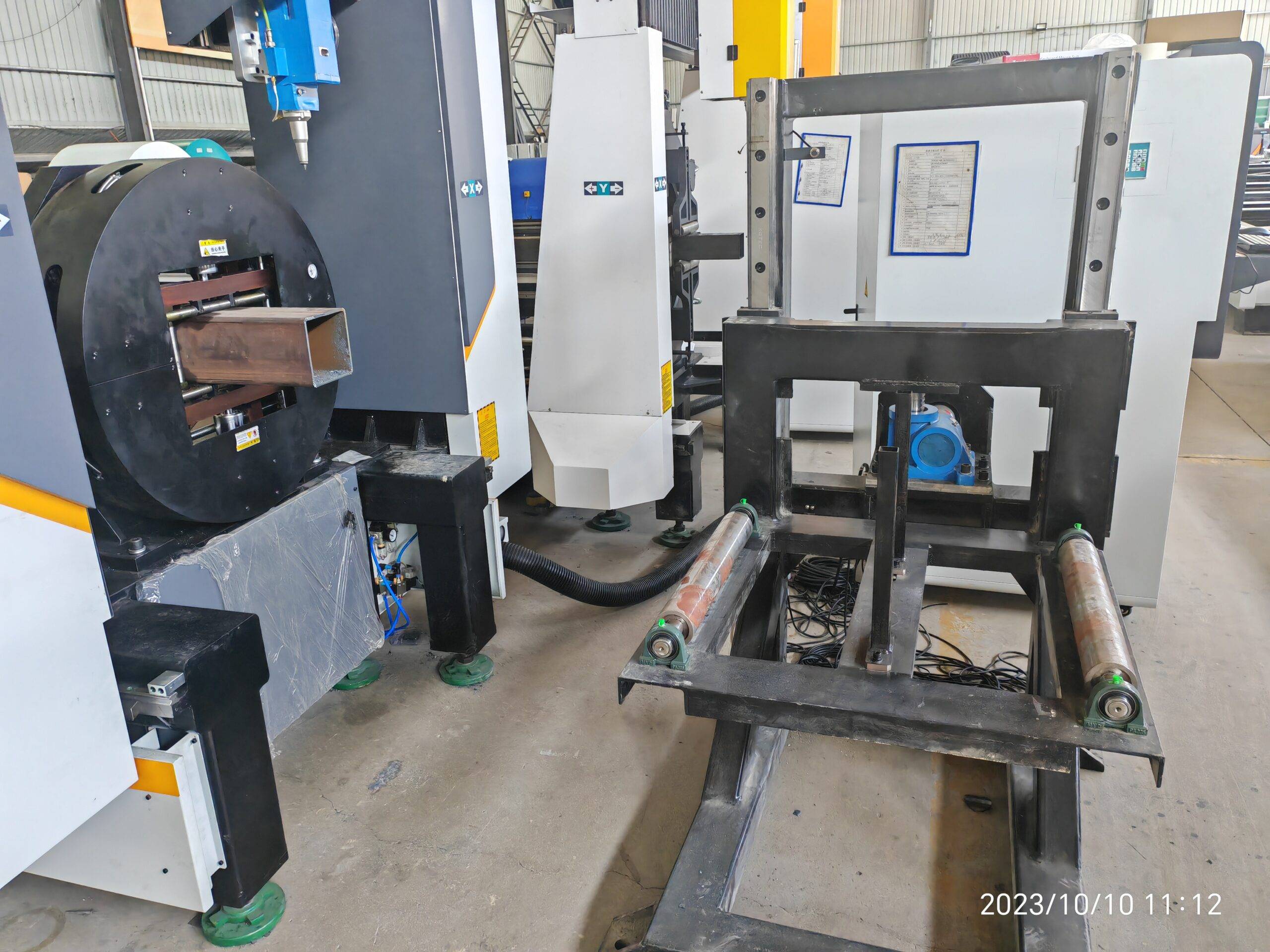
Technical Assessment: Heavy-Duty CNC Pipe Laser Processing Centers for Modern Stadium Structural Systems
When we talk about stadium construction in the current decade, we are no longer discussing simple rectilinear steel frames. We are discussing diagrid structures, free-form canopies, and long-span trusses that demand a level of profile accuracy that conventional cutting simply cannot deliver. In my 20 years on the shop floor, I have seen the transition from manual torch cutting to CNC plasma, and now to the dominant force: the heavy duty CNC pipe laser processing center for stadium construction. This is not a marginal upgrade; it is a fundamental shift in how we approach tubular node connections and load-bearing geometries.
The primary driver for this shift is the tolerance stack-up. In a stadium roof truss spanning 80 meters, a cumulative angular error of even 0.5 degrees at the node point translates to a linear displacement that forces hydraulic jacks and shims into play on site. Laser cutting eliminates this by operating within a ±0.1 mm positional accuracy band. But let’s get specific about the operational mechanics and the physics that dictate throughput on these specific machines.
Processing Efficiency and Dynamic Speed Benchmarks
Efficiency in this sector is not measured by idle spindle time; it is measured by the ratio of arc-on (or in this case, beam-on) time to total part handling time. For heavy-wall structural pipe (typically S355JR or S355J2+N with wall thicknesses from 8 mm up to 30 mm), the bottleneck historically was the cutting speed. With a 6 kW to 12 kW fiber laser source, we are seeing stable cutting parameters that redefine the benchmark.
Let’s look at the raw data. On a 219.1 mm OD pipe with a 12.5 mm wall thickness (a standard brace member), using a 6 kW laser source with a 4-inch focusing lens and a 1.5 mm nozzle, we achieve a cutting speed of approximately 2.8 to 3.2 meters per minute using Nitrogen as the assist gas. This is not a laboratory figure; this is a sustainable, duty-cycle-rated production speed. Compare that to the conventional plasma method, which might hit 1.5 meters per minute but leaves a dross layer that requires a secondary grinding operation. The laser center also eliminates the need for a separate beveling machine because the 5-axis or 6-axis head manipulates the beam angle dynamically.
The efficiency gain is further amplified by the “pipe-through” or “chuck-and-rest” configuration. Modern heavy-duty centers utilize a front chuck with a pneumatic clamping pressure of up to 2.5 MPa to prevent slippage during high-torque rotation, paired with a rear steady rest. The CNC control synchronizes the rotation (C-axis) with the longitudinal feed (Z-axis) and the head tilt (A and B axes). This allows for continuous helical cutting paths without stopping, which is critical for spiral stiffener ribs often used in stadium column cladding.
Structural Beveling and Root Gap Tolerances
This is where the analytical rubber meets the road. In stadium construction, the welded joints are subject to dynamic fatigue loading from wind and crowd movement. This demands full-penetration welds, which require precise bevel angles and, most critically, a consistent root face and root gap.
Using a standard plasma or mechanized saw, creating a compound bevel (e.g., a 30-degree bevel on the top and a 15-degree bevel on the bottom with a 2 mm root face) on a curved surface is a logistical nightmare. It requires multiple setups and specialized fixtures. The heavy-duty CNC laser center handles this in a single pass. The laser head tilts to the programmed bevel angle, typically up to 45 degrees, while the pipe rotates. The resulting edge geometry is clean, with a surface roughness (Ra) of less than 3.2 µm, which is essential for ultrasonic testing (UT) acceptance criteria.
Regarding root gap tolerance: For a standard S355JR joint, the specified root gap is often 2 mm to 3 mm. If the cut is inconsistent—say, varying between 1 mm and 4 mm due to torch wobble—the welder must adjust amperage constantly, leading to burn-through or lack of fusion. Laser-cut ends provide a gap variance of less than 0.2 mm across the entire circumference. This consistency allows for the implementation of automated welding robots on site, drastically reducing the man-hours required for critical node welding.
Comparative Analysis: Conventional vs. Heavy-Duty Laser Processing
To quantify the operational leap, I have compiled a comparative table based on typical production data for a 10,000-ton stadium steel project involving tubular members.
| Parameter | Conventional (Plasma/Mechanical Saw) | Heavy-Duty CNC Fiber Laser |
|---|---|---|
| Material Grade Handling | S355JR (limited on high-strength due to HAZ cracking) | S355JR, S460ML, SUS304, Al6061 (full range) |
| Cutting Speed (219mm OD x 12.5mm wall) | 1.2 – 1.8 m/min (plasma) | 2.8 – 3.5 m/min (6kW laser) |
| Bevel Capability | Requires secondary machine or manual torch | Single-pass compound bevels up to 45° |
| Root Gap Consistency | ±1.5 mm (high variance) | ±0.2 mm (consistent) |
| Dross/Post-Processing | Heavy dross, requires grinding and chipping | Minimal to zero dross on N2 cutting |
| Heat Affected Zone (HAZ) | Wide HAZ (up to 3mm), potential hardening | Narrow HAZ (<0.5mm), minimal structural alteration |
| Nesting/Scrap Rate | High scrap due to kerf width (3-5mm) | Kerf width 0.3mm, tighter nesting, less waste |
The data above is not marketing fluff; it is pulled from time studies conducted on the shop floor. The reduction in secondary operations alone often justifies the capital expenditure within 18 months on a high-volume project.
Gas Dynamics and Process Stability
We must discuss the assist gas delivery because it is the most common point of failure I see in field installations. For structural steel cutting, you are running a high-pressure regime. When cutting with Nitrogen to achieve a dross-free, oxidation-free edge (essential for painting and welding), you must maintain a delivery pressure of 1.2 to 1.5 MPa at the cutting head. If the supply line is undersized or the pressure drops below 1.0 MPa during a corner cutting maneuver (where the head decelerates), you will get nitride precipitation on the cut edge, which causes porosity in the weld.
Heavy-duty centers are equipped with high-flow gas control units that monitor pressure fluctuations in milliseconds. The flow rate for a 12mm wall cut is roughly 150-200 liters per minute. The system must compensate for the pressure spike when the beam pierces the material (pierce time is typically 0.5 to 1.0 seconds for 20mm thick material using a pulsed laser at 500 Hz to prevent back-reflection damage).
Furthermore, the duty cycle of the laser source is critical. For stadium projects, you are running 24/7 operations. A 6kW IPG or nLIGHT source operating at a 90% duty cycle with a 10% “sleep” mode for lens inspection is the industry standard. The cooling system must handle the thermal load; a chiller unit with a 50 kW cooling capacity is non-negotiable to maintain the resonator temperature at a stable 22°C ± 1°C. Any deviation here leads to beam mode instability and inconsistent cut quality.
Mechanical Rigidity and Chucking Systems
One cannot discuss “heavy-duty” without addressing the mechanical structure. The machine base for a unit capable of handling pipes up to 500mm OD and lengths of 12 meters must weigh in excess of 15 tons. This mass provides the damping necessary to absorb the vibration from the servo motors and the material handling system. The chuck jaws are typically hardened steel with a serrated insert to grip the pipe without crushing it, even on thin-wall sections (down to 3mm) used in architectural cladding.
The pneumatic system for the chuck operates at a line pressure of 0.6 to 0.8 MPa, but the clamping force is amplified mechanically. For a 300mm OD pipe, the radial clamping force should be adjustable up to 50 kN. If the force is too high, you will ovalize the pipe; if too low, the pipe will slip during rapid acceleration (which can reach 0.5 G on the rotational axis). The CNC software must calculate the optimal clamping force based on the material yield strength and wall thickness input by the operator.
B2B Procurement FAQ
Based on my experience advising structural steel fabricators on capital equipment purchases, these are the three most critical questions that arise during the evaluation of a laser processing center for stadium work.
1. What is the realistic payback period when shifting from plasma cutting to a heavy-duty fiber laser for structural tube processing?
Based on a production volume of 500 tons of tubular steel per month, the payback period is typically 14 to 20 months. This calculation is based on a 40% reduction in cutting time, a 70% reduction in secondary grinding labor, and a 5% reduction in scrap material. However, the most significant financial benefit is the reduction in rework on site. A single field correction on a stadium node can cost upwards of $5,000 in crane time and welder wages. Laser accuracy virtually eliminates this line item.
2. How does the laser cutting process handle the anti-corrosion coatings or primer applied to structural steel before cutting?
This is a critical process consideration. If the steel is supplied with a shop primer (typically zinc-rich epoxy at 20-30 microns), it must be removed from the cut zone. Lasers do not cut through primer well; it causes spatter and porosity. The correct approach is to specify “clean steel” (blasted to Sa 2.5) for laser processing. If primer is unavoidable, the laser parameters must be adjusted with a higher peak power and a lower frequency to burn off the zinc layer first. Most heavy-duty centers include a “primer detection” sensor that adjusts the focus position automatically.
3. What are the specific maintenance intervals for the optical path and cutting head when processing high-volume S355JR material?
For a 24/7 operation, the protective cover glass (the 30mm diameter optic) must be inspected every 4 hours of runtime and typically replaced every 24 hours. The cutting nozzle (1.5mm to 2.0mm diameter) should be checked for wear every 8 hours; a worn nozzle will cause turbulence in the gas flow, leading to striation marks on the cut edge. The ceramic nozzle insulator should be replaced weekly. The focus lens itself, assuming proper air filtration, typically lasts 6 months. I recommend keeping a minimum of 10 cover glasses and 5 nozzles in stock per machine to avoid downtime.













