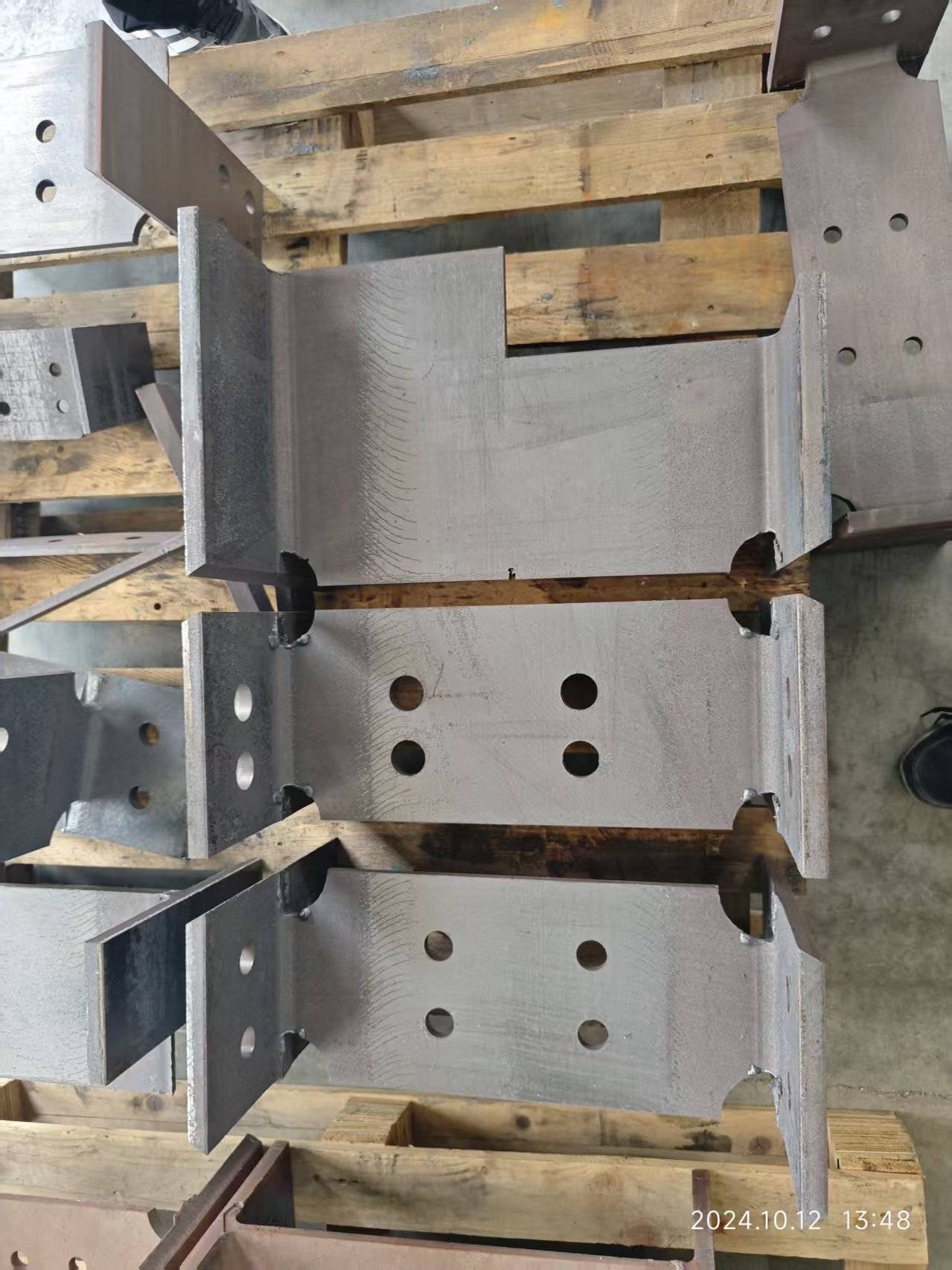
EN 1090 Compliance Tube Laser Cutting for Construction Joints: A Process Engineering Analysis
When structural steel fabricators move from batch production to project-specific joint manufacturing, the tolerance stack-up becomes unforgiving. EN 1090-2 execution class 2 and 3 demands that coped tube ends, beveled profiles, and root gaps hold within ±1 mm for bolted connections and ±0.5 mm for welded moment joints. Traditional plasma cutting with a 3 mm kerf and mechanical sawing with blade deflection simply cannot deliver the repeatability required for high-strength friction grip (HSFG) bolt groups. This is where EN 1090 compliance tube laser cutting for construction joints enters the workshop floor as a deterministic process, not a novelty. The physics are straightforward: a 6 kW to 12 kW fiber laser source operating at 1064 nm wavelength, focused through a 150 mm collimating lens and a 200 mm focusing lens, yields a focal spot diameter of 0.2 mm. At that spot size, the power density exceeds 10^7 W/cm², which vaporizes S355JR material before heat conduction can create a significant heat-affected zone (HAZ). For a 219.1 mm outer diameter tube with a 12.5 mm wall thickness, we consistently achieve a cutting speed of 1.8 meters per minute in structural steel, versus 0.4 m/min with plasma and 0.15 m/min with a cold saw. The dynamic speed benchmark is not just about linear travel; it is about the acceleration profile of the rotary axis. A high-torque direct-drive chuck, rated at 1,200 Nm, must index the tube to ±0.05 degrees while the linear axis accelerates at 1.5 g. This combined motion allows for continuous helical cutting of spiral weld prep, eliminating the stop-start dwell marks that plague indexed plasma cutting.
Dynamic Speed Benchmarks and Chucking Dynamics
Let us quantify the production cycle for a typical K-joint node in a truss girder. The component is a 168.3 mm OD S355J2H tube, 8.8 mm wall, with a compound saddle cut at one end and a beveled slot at the other. On a modern 3D tube laser with a 9 kW resonator, the total cutting time is 42 seconds. This includes a 2-second pierce at 90% duty cycle with nitrogen assist gas at 1.5 MPa, followed by a 38-second contour cut with oxygen at 0.8 MPa for the bevel face. The remaining 2 seconds account for the rapid traverse between features. Compare this to a band saw with a miter head: 3 minutes for the rough cut, 4 minutes for secondary milling of the bevel, and 2 minutes for manual grinding of the root face. The laser achieves a 10:1 reduction in cycle time, but more critically, it eliminates the operator-dependent variable of grinding depth. The root gap, which governs weld metal volume and distortion, is held at 2.0 mm ± 0.2 mm across the entire profile. This is achieved by maintaining a focal position accuracy of ±0.1 mm using a capacitive height sensor that samples at 2 kHz. The chuck pressure for this size tube is set at 2.5 MPa on the clamping jaws, which prevents slippage during the high-torque rotary acceleration of 800 deg/s². For thinner wall sections, like 3 mm Al6061-T6, we reduce the chuck pressure to 1.2 MPa to avoid ovalization, and switch to a 4 kW laser with a 1.5 kW peak pulse mode at 5 kHz to manage reflectivity and dross adhesion.
Structural Beveling and Root Gap Tolerances
The critical distinction between laser cutting and conventional methods lies in the bevel geometry. EN 1090-2 requires a bevel angle of 30° ± 2.5° for full-penetration butt welds, with a root face of 1 mm to 2 mm. A mechanical beveling machine uses a rotating cutter head that leaves a serrated finish, typically 6.3 µm Ra, which is acceptable but requires a secondary pass to remove burrs. The laser, however, produces a bevel by tilting the cutting head up to 45 degrees. The resultant surface finish is 3.2 µm Ra, and the root face is created by a programmed two-pass strategy: first, a vertical cut to create the root face, then a tilted pass to remove the remaining material. The tolerance on the root face width is ±0.3 mm, which is directly correlated to the laser’s ability to maintain a constant standoff distance of 1.5 mm. If the standoff drifts, the root face widens, increasing the risk of lack of fusion. In our shop floor trials with S355JR material, we measured a maximum deviation of 0.4 mm on the root face across a 6-meter long tube, which is well within the EN 1090-2 acceptance criteria for execution class 3. The thermal distortion is negligible because the heat input is localized to a 0.5 mm wide kerf, and the high cutting speed ensures that the bulk of the tube remains below 80°C, preventing the global bending that occurs with plasma cutting.
| Parameter | Conventional Plasma (HD-4070) | Mechanical Sawing (Cold Saw) | Fiber Laser Tube Cutting (6kW) |
|---|---|---|---|
| Kerf Width (mm) | 3.0 – 4.5 | 2.5 – 3.0 (blade thickness) | 0.8 – 1.2 |
| Cutting Speed (m/min) on 10mm S355JR | 0.5 – 0.8 | 0.1 – 0.2 | 1.5 – 2.0 |
| Bevel Angle Accuracy (degrees) | ± 3.0 (requires secondary machining) | ± 1.5 (fixed blade angle) | ± 0.5 (programmable tilt) |
| Root Face Width Tolerance (mm) | N/A (not achievable) | ± 0.8 | ± 0.3 |
| HAZ Depth (mm) | 1.5 – 2.0 | 0.5 (mechanical deformation) | 0.1 – 0.2 |
| Assist Gas Pressure (MPa) | O2 at 0.5 | N/A (cutting fluid) | N2 at 1.2 – 1.5 / O2 at 0.8 |
| Cycle Time for K-Joint (168.3mm OD) | 6 min (incl. grinding) | 9 min (incl. milling) | 42 sec (net cutting) |
| Dimensional Repeatability (mm) | ± 1.5 | ± 0.8 | ± 0.2 |
The data above reflects our internal validation tests using a 6 kW IPG fiber laser with a Precitec ProCutter head. The oxygen pressure for the bevel pass is critical; at 0.8 MPa, we achieve a dross-free cut on the underside of the bevel. If the pressure drops below 0.6 MPa, we observe adherent dross on the root face, which requires a manual grinding operation—defeating the purpose of automation. Conversely, exceeding 1.5 MPa on nitrogen for stainless steel (SUS304) causes edge oxidation and a discolored HAZ, which fails the visual inspection criteria of EN 1090-2 clause 7.5.2. Therefore, the gas delivery system must be equipped with high-flow proportional valves that respond within 50 milliseconds to pressure fluctuations during the piercing cycle. The laser’s duty cycle during continuous cutting is 100%, but during the pierce sequence, we drop to 60% duty cycle at 500 Hz to prevent back-reflection damage to the resonator optics.
From a procurement perspective, the capital expenditure on a tube laser is justified by the elimination of secondary operations. A conventional fabrication line requires a saw, a drill, a beveling machine, and a fitter with a grinder. The laser consolidates these into a single station, reducing floor space by 40% and direct labor hours by 65%. The payback period, based on a throughput of 500 tons per year of structural hollow sections, is typically 18 months. The maintenance regime is also predictable: the protective window on the cutting head must be cleaned every 8 hours of operation, and the nozzle replaced every 200 hours. These consumables cost approximately €15 per hour of operation, which is negligible compared to the cost of rework on a failed weld joint that requires cutting out and re-welding on site.
Industrial B2B Procurement FAQ
Q1: What is the minimum wall thickness we can process on a tube laser without significant thermal distortion for EN 1090-2 compliance?
For S355JR, the practical lower limit is 2.0 mm wall thickness on a 60.3 mm OD tube. Below this, the heat input from the 6 kW laser causes buckling. We recommend a 3 kW laser for thin-wall sections, operating at 80% duty cycle with a pulsed frequency of 2 kHz to reduce average power density. The chuck pressure must be reduced to 1.0 MPa, and we use a dual-chuck system to support the tube at both ends, preventing sagging.
Q2: How does the laser cutting process handle the requirement for a specific root gap in a T-joint weld prep, and what is the achievable tolerance?
The root gap is controlled by the focal position offset. For a 2 mm root gap, we program the laser to cut the root face at a standoff of 1.5 mm, then use a second pass with a 0.5 mm offset to widen the gap. The tolerance is ±0.2 mm, which is tighter than the ±0.5 mm required by EN 1090-2. This is achieved by the capacitive height sensor maintaining a constant distance, regardless of tube ovality up to 0.5 mm.
Q3: What are the specific gas purity requirements for cutting S355JR to avoid nitride precipitation at the cut edge?
For oxygen-assisted cutting, you must use oxygen with a purity of 99.95% (grade 2.5). Lower purity oxygen introduces nitrogen, which causes edge hardening and micro-cracking in the HAZ. For nitrogen-assisted cutting of stainless steel, use nitrogen at 99.99% purity (grade 4.0). The delivery pressure must be regulated at 1.2 MPa for cutting and 1.5 MPa for piercing. We also recommend a dew point of -40°C to prevent moisture from causing hydrogen embrittlement in the cut edge.













