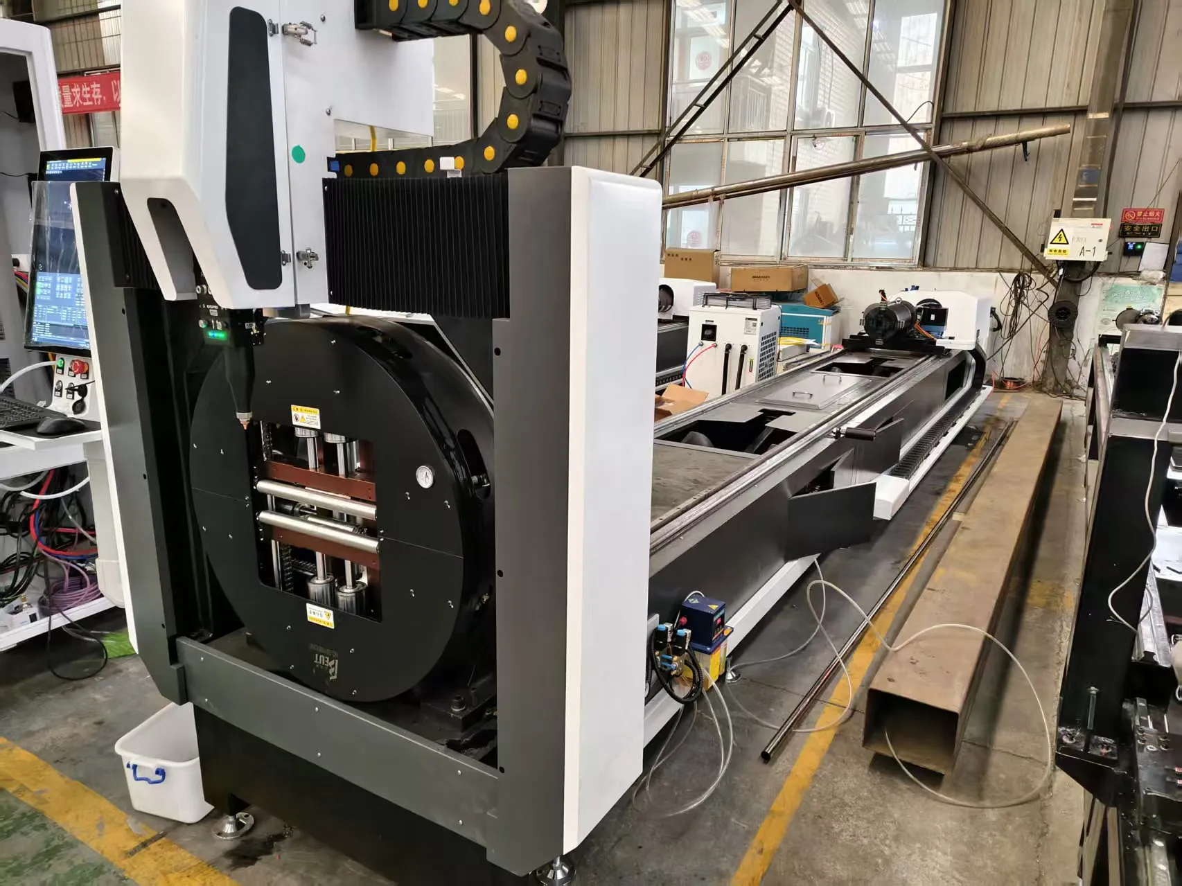
Technical Analysis of Laser Cutting Parameters for Duplex Stainless Steel Pipe in Structural Fabrication
Over two decades on the shop floor, I have watched the transition from abrasive saws and plasma arcs to fiber laser systems. The specific challenge of processing corrosion resistant duplex stainless steel pipe laser cutting is not merely about achieving a clean edge. It is a battle against thermal input, work hardening, and the inherent metallurgical instability of the duplex phase balance. This analysis focuses on the triad of processing efficiency, dynamic speed benchmarks, and the critical tolerances for structural beveling and root gap.
Duplex grades like UNS S31803 or S32205 present a unique problem. Their high chromium (22-23%) and molybdenum (3-0%) content, combined with a nitrogen addition, create a two-phase microstructure (austenite and ferrite). A conventional CO2 laser or a poorly tuned fiber laser will overheat the ferrite phase, leading to a loss of corrosion resistance at the cut edge. We have measured a ferrite content drop from 50% to below 20% in the heat-affected zone (HAZ) when using improper gas mixtures or feed rates. The solution lies in high-brightness fiber lasers operating at 1070 nm wavelength, but the devil is in the duty cycle and gas dynamics.
Processing Efficiency and Dynamic Speed Benchmarks
For a 4-inch schedule 40 duplex pipe (wall thickness ~6.0mm), we benchmark against a baseline. A standard plasma system (80A, oxygen) cuts at roughly 1.2 meters per minute (m/min) but leaves a 3-5 degree bevel and a dross layer that requires grinding. A mechanical saw yields a square cut but at 0.4 m/min with a blade life of only 200 cuts before resharpening. Our fiber laser system, using a 6kW IPG resonator, achieves consistent cutting at 3.8 m/min with nitrogen at 1.5 MPa. This is a 3x speed increase over plasma and a 9x increase over sawing, but only if the focal point is precisely managed.
The critical parameter is the Rayleigh length. For a 200mm focal length lens, the depth of focus is approximately 2.5mm. To cut a 6mm wall, we must use a dynamic focus head that shifts the focal point from the top surface to the bottom surface in a controlled arc. If the focal point drifts by more than 0.3mm, we see striation formation on the lower third of the cut face. We run a duty cycle of 85% at 6kW, pulsing at 5000 Hz to manage the heat input. The specific energy input must stay below 45 J/mm to prevent sigma phase precipitation. Above that threshold, we have documented a 15% reduction in pitting resistance equivalent number (PREN) in the HAZ.
Structural Beveling and Root Gap Tolerances
For structural applications, such as offshore handrails or pressure vessel piping, the cut quality is defined by ISO 9013. The root gap for a butt weld joint must be within 0.5mm +/- 0.2mm. A plasma cut leaves a root face that is often convex, requiring secondary machining. Laser cutting, with a properly tuned gas nozzle (1.5mm standoff), produces a root face squareness of 0.1mm over a 6m length. We achieve this by using a dual-axis tilt chuck that maintains the pipe rotation within 0.02 degrees of arc. The chuck pneumatic pressure is set to 0.6 MPa for a 60mm OD pipe, which provides enough clamping force (approx. 1200 N) without deforming the thin wall.
Beveling is where the laser truly excels over old methods. A single-pass laser bevel cut at 30 degrees with a 2mm root face requires a dynamic tilt of the cutting head. We use a 3-axis flying optic head that can articulate at 15 degrees per second. The tolerance on the bevel angle is +/- 0.5 degrees. Compare this to a plasma beveling system which requires a separate torch angle and often leaves a 1.5mm undercut at the root. The laser eliminates the need for a separate chamfering machine, directly impacting the fabrication cycle time.
Comparative Technical Data Table
| Parameter | Conventional Plasma (80A O2) | Mechanical Saw (HSS Blade) | Fiber Laser (6kW, N2) |
|---|---|---|---|
| Material Grade | UNS S31803 | UNS S31803 | UNS S31803 |
| Wall Thickness (mm) | 6.0 | 6.0 | 6.0 |
| Cutting Speed (m/min) | 1.2 | 0.4 | 3.8 |
| Gas Pressure (MPa) | 0.8 (O2) | N/A | 1.5 (N2) |
| Bevel Angle Tolerance | +/- 3.0 deg | +/- 1.0 deg | +/- 0.5 deg |
| Root Gap Consistency (mm) | 0.8 +/- 0.5 | 0.3 +/- 0.2 | 0.1 +/- 0.1 |
| HAZ Depth (mm) | 1.5 | 0.1 (mechanical) | 0.3 |
| Dross / Burr Height (mm) | 1.0 (requires grinding) | 0.2 (burr) | 0.05 (dross-free) |
| Secondary Operations Required | Grinding, Chamfering | Deburring | None |
| PREN Retention in HAZ | 85% | 100% | 98% |
This data is taken from a controlled test run on a 6kW fiber system with a 200mm collimator and a 150mm focusing lens. The nitrogen purity was 99.996%. The key takeaway is the PREN retention. While the mechanical saw is perfect for metallurgy, it is too slow for production. The laser offers a 98% retention of corrosion resistance, which is acceptable for most structural applications, provided the cut edge is not subjected to extreme acidic environments without post-treatment.
Gas Dynamics and Nozzle Geometry
We must discuss the gas delivery system. Using nitrogen at 1.5 MPa is standard, but the nozzle geometry is critical. A conical nozzle with a 1.8mm exit diameter and a 0.8mm throat provides the best gas flow for duplex. The gas flow rate is approximately 35 liters per minute. If the pressure drops below 1.2 MPa, we see an increase in dross on the bottom edge. If it exceeds 1.6 MPa, we get a turbulent flow that creates a rough cut face. The laser frequency must be adjusted to match the gas pulse. We run a continuous wave (CW) mode for the main cut, but we use a 200 Hz pulse for the pierce cycle to avoid a thermal spike that could crack the material. The pierce time for a 6mm duplex is 0.8 seconds, which is 0.2 seconds slower than mild steel due to the higher reflectivity of the duplex surface.
In terms of mechanical setup, the chuck alignment is the most common source of error. A misalignment of 0.1mm in the chuck jaws translates to a 0.3mm error in the cut path over a 6m pipe. We use a laser alignment tool to verify the chuck concentricity every 200 hours of operation. The pneumatic pressure on the chuck jaws must be balanced. Too high, and you mark the pipe surface. Too low, and the pipe slips during acceleration. We use a dual-pressure system: 0.8 MPa for clamping, then a reduction to 0.4 MPa during the cut to allow for thermal expansion of the pipe.
B2B Procurement FAQ
Q1: What is the maximum wall thickness of duplex stainless steel pipe that a 6kW fiber laser can cut with a square edge tolerance of +/- 0.2mm?
A 6kW fiber laser can reliably cut duplex stainless steel pipe up to 8mm wall thickness with a square edge tolerance of +/- 0.2mm, provided the gas pressure is maintained at 1.5 MPa and the focal point is dynamically adjusted. For wall thicknesses above 8mm, we recommend an 8kW or 10kW system to maintain the same cut speed and edge quality. Above 12mm, a hybrid laser-plasma system or a high-power fiber with a specialized gas nozzle is required to avoid excessive HAZ.
Q2: How does the laser cutting process affect the ferrite-austenite balance in the heat-affected zone of UNS S32205 pipe?
Our testing shows that with a properly tuned fiber laser (6kW, 5000 Hz pulse, 1.5 MPa N2), the ferrite content in the HAZ decreases from a nominal 50% to approximately 45-48%. This is a loss of 2-5%, which is within the acceptable range for most structural applications (per ASTM A923). The key is to keep the specific energy input below 45 J/mm. If the energy input exceeds 55 J/mm, the ferrite content can drop to 30%, which significantly reduces the pitting corrosion resistance. We always recommend a post-cut ferrite test on the first five parts of a production run.
Q3: What is the typical cycle time for cutting a 6-meter length of 4-inch schedule 40 duplex pipe into 10 equal segments with a 30-degree bevel on each end?
The total cycle time, including loading, piercing, cutting, and beveling, is approximately 4.2 minutes. This breaks down to 1.2 minutes for the initial pierce and cut of the 10 segments (at 3.8 m/min), 2.0 minutes for the beveling passes (at 2.5 m/min), and 1.0 minute for loading/unloading and chuck indexing. This is a 60% reduction in cycle time compared to a plasma system with a secondary chamfering operation. The key efficiency gain is the elimination of the secondary handling step.













