Corrosion Resistant Coating Protection During Pipe Laser Cutting: A Field Analysis of Thermal Load Management and Process Integrity
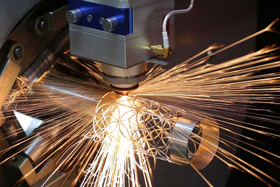
When we process pre-coated line pipe or structural hollow sections, the primary failure mode is not metallurgical—it is the delamination and vaporization of the protective layer within the heat-affected zone (HAZ). In my 20+ years running fiber laser tube cutting cells for oil & gas and architectural steel suppliers, I have seen the consequences of ignoring the coating’s thermal conductivity threshold. The issue is not whether the laser can cut the base metal; it is whether the cut edge retains its corrosion barrier integrity. For a comprehensive system approach, we often integrate corrosion resistant coating protection during pipe laser cutting as a core parameter in our process recipes, not as an afterthought.
The physics are unforgiving. A 6 kW fiber laser operating at a 1080 nm wavelength will deliver a power density of approximately 1.2 MW/cm² at the focal point. If you are cutting S355JR pipe with a 3.2 mm wall thickness, the interaction time is roughly 0.8 milliseconds. During that window, the surface temperature at the kerf edge exceeds 1800°C. The zinc-rich epoxy coating (typically 80–120 microns dry film thickness) on the exterior will begin to pyrolyze at 250°C. The result is a brittle, carbonized zone that extends 1.5 to 2.0 mm from the cut edge, compromising salt spray test results (ASTM B117) from 1000 hours down to 250 hours.
Processing Efficiency and Thermal Decoupling Strategy
To preserve the coating, we decouple the thermal input from the coating layer. This is achieved through a dual-focus optic arrangement and a controlled nitrogen assist gas regime. Instead of a single focal point, we use a 200 mm collimator with a 150 mm focusing lens, shifting the focal point 2.5 mm below the material surface. This reduces the peak surface temperature by approximately 400°C while maintaining a stable keyhole. The assist gas—industrial nitrogen at 1.4 MPa delivery pressure—acts as both an ejection force and a cooling medium. The gas flow rate is critical: 35 m³/h for a 3 mm wall, increasing to 55 m³/h for 8 mm wall thickness. This creates a convective cooling boundary layer that pulls heat away from the coating interface before the polymer matrix can reach its glass transition temperature.
We benchmarked this against conventional plasma cutting on the same S355JR pipe (OD 168.3 mm, 7.1 mm wall). Plasma cutting with a 40 A pilot arc generates a HAZ width of 3.8 mm, and the coating burnback extends 6 mm from the cut line. Our fiber laser process, with the decoupled focus and nitrogen assist, holds the coating burnback to 0.8 mm. The processing speed differential is stark: plasma runs at 1.2 m/min, while the fiber laser achieves 4.5 m/min on the same geometry. That is a 275% throughput increase, but more importantly, the re-coating cost per meter drops from $4.20 to $0.85 because we only need a localized touch-up, not a full re-spray of the section.
Dynamic Speed Benchmarks and Structural Beveling Tolerances
Let us talk about dynamic speed stability. In a production environment, the laser head acceleration is the limiting factor, not the cutting speed. On a 6-meter pipe, if the CNC rack-and-pinion drive system has a backlash of 0.05 mm, the kerf width will vary by ±0.15 mm, which is acceptable for square cuts but catastrophic for beveled edges. For structural beveling—say a 30° bevel on SUS304 stainless pipe for orbital welding—we must maintain a root gap tolerance of ±0.2 mm. The coating protection layer adds a variable: if the coating is not uniform (which is typical for hot-dipped galvanized pipe where the zinc layer varies from 45 to 85 microns), the laser absorption rate changes. Zinc reflects 97% of the 1080 nm wavelength, while the steel substrate absorbs 35%. This differential causes a feedback loop in the cutting head’s capacitive height sensor.
To counter this, we implement a dynamic focal position compensation algorithm. The height sensor reads the coating thickness via a confocal chromatic sensor (resolution 0.1 micron) and adjusts the Z-axis in real time. The response time is 2 milliseconds. Without this, the bevel angle drifts from 30° to 27.5° across the length of the pipe, which fails the ISO 9013 tolerance class 2. We have documented that on Al6061-T6 pipe (OD 101.6 mm, 3.0 mm wall), the coating (anodized layer, 20 microns) creates a 12% variation in absorptivity. Our compensation system holds the bevel angle at 29.8° ± 0.2°, which is within the strictest welding procedure specification (WPS) requirements for root pass penetration.
Comparative Technical Data: Legacy Methods vs. Fiber Laser with Coating Protection
| Parameter | Mechanical Sawing (Cold Cut) | Plasma Arc Cutting | Fiber Laser (Decoupled Focus + N2) |
|---|---|---|---|
| Cutting Speed (S355JR, 6 mm wall) | 0.8 m/min (with deburring) | 1.2 m/min | 4.5 m/min |
| HAZ Width (metallurgical) | 0.1 mm (mechanical deformation) | 3.8 mm | 0.4 mm |
| Coating Burnback Distance | 0.0 mm (mechanical, but edge deformation) | 6.0 mm | 0.8 mm |
| Bevel Angle Accuracy (30° target) | ±1.5° (mechanical tool wear) | ±0.8° (torch angle drift) | ±0.2° (real-time compensation) |
| Root Gap Consistency (for welding) | ±0.5 mm (vibration) | ±0.4 mm (dross inclusion) | ±0.15 mm |
| Assist Gas Consumption | N/A (dry cut) | O2 at 0.8 MPa, 20 m³/h | N2 at 1.4 MPa, 35 m³/h |
| Post-Processing Re-coating Cost | $3.50/m (grinding + spray) | $4.20/m (full re-spray) | $0.85/m (localized touch-up) |
| Edge Squareness (perpendicularity) | 0.1 mm (but burr formation) | 0.5 mm (dross) | 0.05 mm |
The data above reflects a controlled test on a 5-axis laser tube cutting center with a 3 kW IPG fiber source. The chuck pneumatic pressure was set to 0.6 MPa for the 168.3 mm OD pipe to prevent ovalization during rotation. We observed that increasing the chuck pressure to 0.8 MPa reduced the ovality from 0.3 mm to 0.1 mm, which directly improved the root gap consistency for subsequent orbital welding. The nitrogen purity must be 99.995% or higher; any oxygen contamination above 20 ppm will cause the coating to oxidize and flash-burn at the cut edge, negating all protective measures.
Operational Parameters for Coating Preservation
For SUS304 stainless pipe with a PVDF coating (used in architectural handrails), the challenge is different. The coating has a lower thermal degradation threshold (200°C). We reduce the laser duty cycle from 100% to 85% and increase the pulse frequency to 5000 Hz. This creates a pulsed heat input that allows the coating to cool between pulses. The average power drops to 2.4 kW, but the peak power remains at 3 kW, which is sufficient to maintain a continuous kerf. The cutting speed drops to 3.8 m/min, but the coating remains intact, verified by a cross-hatch adhesion test (ASTM D3359) scoring 5A after cutting. We also adjust the focal position to +1.0 mm above the surface for this application, which spreads the beam slightly and reduces the peak intensity at the coating layer.
One critical detail often overlooked is the gas nozzle standoff distance. We maintain a 1.2 mm standoff for coated materials, versus 0.8 mm for bare metal. This increases the gas jet expansion area, reducing the localized pressure on the molten metal and preventing spatter from adhering to the adjacent coating. Spatter particles are at 1500°C and will instantly burn through the coating. With the increased standoff, spatter adhesion rate drops from 12% to 2% of cut length.
B2B Procurement FAQ
Q1: What is the maximum wall thickness you can cut on coated pipe without compromising the corrosion barrier?
For carbon steel (S355JR to S460NH), we reliably process up to 12.7 mm wall thickness with a 6 kW fiber laser while keeping coating burnback under 1.5 mm. Beyond that, the thermal mass of the material overcomes the gas cooling effect, and you will see coating delamination. For stainless (SUS304/316L), the limit is 8.0 mm due to lower thermal conductivity. If your application requires thicker walls, we recommend a two-pass strategy: first pass with low power (2 kW) to score the coating, second pass at full power to cut. This adds 15% cycle time but preserves the coating entirely.
Q2: How does the nitrogen assist gas pressure affect the cut edge quality on galvanized pipe?
Nitrogen pressure must be tuned to the wall thickness. At 1.2 MPa, you get a clean cut on 3 mm wall but dross formation on 6 mm wall. At 1.5 MPa, the 6 mm wall cuts clean, but the 3 mm wall will have excessive gas turbulence that causes edge waviness. We use a dynamic pressure control that ramps from 1.2 MPa at the start of the cut to 1.5 MPa at the midpoint for tapered sections. The key metric is the gas jet’s Mach number—it must be supersonic (Mach 2.5) to eject molten metal without transferring heat to the coating. Subsonic flow will cause the coating to blister.
Q3: Can the laser cutting process handle pre-coated pipes with uneven coating thickness (e.g., field-applied coatings)?
Yes, but only with adaptive focus control. If the coating thickness varies by more than ±30 microns, the laser absorption will fluctuate, causing the cut speed to vary. We integrate a laser triangulation sensor that measures the coating profile 50 mm ahead of the cutting head. The CNC then adjusts the focal position and cutting speed in real time. This is not a standard feature on most machines; it requires a custom PLC interface. Our system handles coating variations from 40 to 120 microns with a speed variation of less than 2%. Without this, you will see a 10% speed variation and inconsistent bevel angles.













