Metallurgical Boundary Conditions in Seamless Carbon Steel Linepipe Processing
Seamless carbon steel linepipe destined for oil and gas gathering, transmission, and process piping places tight constraints on cut quality. Materials specified to API 5L X52 through X80 exhibit carbon equivalents in the 0.40–0.50 range, requiring cutting processes that limit heat input to preserve the normalized, fine-grained microstructure. Traditional cold saws and abrasive wheels produce heavy burr, work-harden the cut face, and force secondary machining. Plasma cutting, while fast, generates a wide heat-affected zone and an oxide-laden bevel face that must be ground back extensively before welding—an unacceptable drag on project schedules where weld inches often exceed a kilometer per module. The precision demands of automated pipe spooling, with its compound bevels, tight length tolerances (±0.5 mm on overall spool length), and the need to certify each heat of steel from remnant inventory, call for a fundamentally different processing platform.
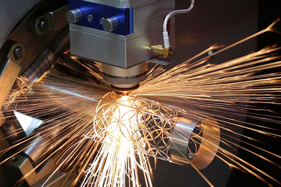
Heavy‑Duty Tube Laser as a Single‑Step Profiling Cell
The shift to a heavy duty tube laser for seamless carbon steel line pipe collapses sawing, facing, beveling, and marking into one station. Modern fiber‑laser sources in the 6 kW to 12 kW range, coupled to 5‑axis interpolating bevel heads (±60° tilt, 360° continuous rotational axis), can process walls up to 25 mm (1 inch) in carbon steel while maintaining a kerf width of 1.2 mm to 1.8 mm. The real untapped value, however, lies not in the photon delivery but in the algorithmic brain that drives the beam path. For companies running thousands of tons of linepipe annually, the difference between 82% and 96% material yield is tens of millions of dollars in raw stock, and that delta is entirely governed by the nesting and cutting strategy software.
Advanced Nesting Algorithms: The Kernel of Material Yield
First‑generation tube‑laser software treated each part as an isolated entity, dropping it onto a pipe length with fixed leading and trailing scrap allowances. Modern production nesting engines utilize constraint‑based combinatorial optimization that simultaneously solves for part orientation, sequencing, and shared‑cut adjacency across the entire pipe inventory. Key inputs include the bill of materials with priority deadlines, on‑hand remnants tagged by heat number, and the full geometric description of each spool end—beam‑straight, single‑V, compound Y, or K‑prep for full‑penetration welds. The algorithm then constructs a directed graph of possible lay‑together candidates, assigning a cost function that weights raw material cost, remnant value, and machine‑axis non‑productive time.
True‑shape nesting within the cylindrical domain goes far beyond simple 2D bin packing. Because a heavy‑duty tube laser can both translate and rotate the pipe relative to the fixed bevel head, parts can be rotated 360° around the pipe axis to align bevel planes away from interference zones. The solver accounts for the minimum gripper zone at the chuck (typically 200 mm to 300 mm) and the tailstock dead zone, ensuring every usable inch of a random‑length pipe gets evaluated.
Common‑Line Cutting Strategy Applied to Beveled Contours
Common‑line cutting is the single most aggressive lever for yield improvement. Instead of leaving a web of material between two adjacent part contours and performing two separate cuts, the software identifies pairs or chains of parts that share an identical boundary. A single laser traverse separates part A from part B, with the path geometry selected such that the left side of the kerf delivers the required bevel angle and root face for part A, while the right side simultaneously satisfies the complementary preparation for part B.
On heavy‑wall carbon steel, this demands kinematic sophistication. Consider a scenario where a 24″ OD × 0.750″ wall pipe requires a 30° external bevel on the outgoing part and a 30° internal bevel on the incoming part. The algorithm evaluates whether the kerf’s V‑shaped relief can satisfy both profiles by offsetting the beam’s focal point and adjusting the head tilt angle mid‑cut, using a variable‑amplitude oscillation pattern. If the pair is geometrically incompatible—say one part demands a J‑groove while the adjacent part requires a square butt finish—the solver will not force a common line and will instead place that pair with a minimal‑waste fill piece, or on a different pipe length altogether. Dynamic lead‑in and lead‑out pulsing prevents crater defects at the shared corner, and the post‑processor suppresses slug‑tag breaks by controlling the piercing sequence at the edge of the common line.
From a thermal perspective, common‑line cutting halves the linear heat input per unit of joint circumference. On susceptibility to cold cracking in X70 and X80 grades, this reduction in successive reheating cycles minimizes the hardness increase at the fusion boundary, keeping micro‑hardness below the 350 HV threshold often specified by end users. The tactic also slashes assist‑gas consumption proportionally.
Material Yield Maximization: A Clinical Comparison
To ground the discussion, consider a fabricator processing 500 metric tons of API 5L X65 seamless pipe per month, with random lengths from 10.5 m to 12.8 m. Spool dimensions range from 600 mm to 2,000 mm, with a mix of straight cuts and beveled ends. Using a band‑saw‑and‑manual‑beveler workflow, typical yield after accounting for remnant drop‑offs, saw‑cut loss, and bevel‑land waste sits at 78% to 82%. Introducing a heavy‑duty tube laser with basic single‑part‑per‑pipe nesting lifts yield to 88% simply by enabling remnant scheduling. Enabling the full common‑line and true‑shape engine, coupled with an inventory‑aware remnant databank, pushes sustained yield to 94%–97%.
The arithmetic: at a delivered pipe cost of approximately $1,800 per metric ton, every percentage point of yield improvement saves $9,000 per month. Over a 36‑month capital amortization horizon, the software‑driven yield delta alone covers the machine investment before factoring in the elimination of downstream grinding and fit‑up corrections. Indirect gains accrue from reduced material certification paperwork, as fewer heat‑code fragments need individual positive material identification.
Operator‑In‑The‑Loop and Shop‑Floor Integration
Yield optimisation is not a purely offline exercise. The HMI of the tube laser must present a live remnant catalogue, allowing the operator to pull a remnant from the rack, scan its barcode, and have the software immediately re‑cluster the day’s production queue around that available piece. Advanced systems support dynamic re‑nesting triggered by real‑time quality data—if a pipe is rejected after loading due to a detected lamination, the scheduler recomputes the optimal cut plan without dismissing the operator to a programming workstation. Similarly, the software ties into enterprise MRP to prioritise parts by vessel release date, ensuring that the highest‑value outcome balances yield with on‑time delivery.
Summary of Engineering Impact
Advanced nesting algorithms and common‑line cutting transform the heavy‑duty tube laser from a dimensional metal‑cutting tool into a closed‑loop material optimisation system. For seamless carbon steel linepipe, where raw material represents 60% to 70% of project cost, the technology compresses the scrap fraction to levels previously achievable only in flat‑plate sheet metal. Combined with single‑piece flow for beveling, the technology redefines how project‑driven fabricators approach mass customisation of piping components.
Industrial Procurement FAQ
The improvement depends on the mix of part lengths and bevel complexity. In controlled audits on 20‑inch OD, 0.875‑inch wall API 5L X65 pipe, fabricators moving from a band‑saw/ dedicated beveler workflow (typical yield 80%–82%) to a tube laser running full common‑line and remnant optimisation have documented sustained yields of 94%–96%. That delta translates to a scrap reduction of roughly 14 percentage points, or 140 fewer tons of waste per 1,000 tons processed.
When the laser’s active power ramp, assist‑gas pressure, and oscillating head trajectory are tailored to the specific alloy, the surface finish of the common‑line face is indistinguishable from a conventionally cut single‑part bevel. Cross‑sectional metallography on X70 material shows a uniform heat‑affected zone width between 0.15 mm and 0.25 mm, with no detectable centreline segregation cracking at the shared boundary. The hardness profile remains within the band of a standard single‑pass laser cut, and subsequent qualification of procedure qualification coupons has repeatedly yielded Charpy and CTOD results that satisfy project requirements.
Modern systems employing 10 kW–12 kW fibre lasers and high‑pressure nitrogen assist routinely process 25 mm (1.0 inch) wall carbon steel with square‑cut feed rates above 0.8 m/min and bevel profiles at proportionally lower speeds. The practical economic ceiling for common‑line beveling of API 5L grades is around 30 mm wall, beyond which multi‑pass flame or plasma processes become competitive. However, the software algorithms manage the inter‑pass dwell and preheat requirements if a single‑pass laser cut is not viable, ensuring that even on 40 mm walls the tube laser can apply a high‑precision root face that requires only a single welding pass to complete the joint prep.


