The Unseen Precision War in Bunk Bed Tube Processing
Walk into any large-volume bunk bed factory and you’ll hear it before you see it: the rhythmic thud of band saws, the chatter of milling fixtures, the piercing screech of drill presses chewing through ERW mild steel tube. A typical double-deck frame swallows 18 to 24 metres of 30×30×1.2 mm or 40×40×1.5 mm S235 structural hollow section. Every cut, every dowel bore, every mitered slat slot used to mean a gang of single-purpose machines and manual handling between stations. The hidden cost was never the cycle time of the individual operation—it was the accumulated tolerance stack and the 3-5% scrap rate from ovalized ends, burred holes, and misaligned T-joint interfaces that wouldn’t flat-pack without a sledgehammer. The industry’s quiet pivot toward bunk bed steel tube laser cutting and drilling automation rewrites that arithmetic.
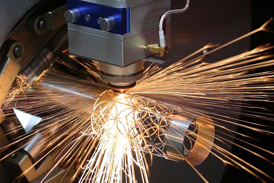
A dedicated laser tube cell now combines raw stock loading, 3D laser cutting, in-line tapping or mechanical drilling, and unload sorting in a single 45-second floor-to-floor sequence. The cell doesn’t just replace machines; it erases the downstream assembly grief caused by inconsistent fit-up. When the tube’s final geometry is born inside the same clamping cycle, the slot and the mating tongue emerge with a gap deviation under 0.15 mm, every time. In practice, that means the welders stop reaching for the grinders. Manufacturers who move beyond the band saw paradigm discover quickly that the real enabler is a tightly synchronised, sensor-rich bunk bed steel tube laser cutting and drilling automation platform that treats the workpiece not as a static extrusion but as a dynamic body subject to clamping strain, inertial torque, and localised thermal expansion.
Process Chain Consolidation: The Laser-Cell Architectural Shift
The old process plan for a bunk bed rail component looked like a factory layout diagram: (1) cut to length plus 2 mm stock allowance, (2) end face milling to finished length, (3) drill four bolt holes, (4) mill two interlocking slots, (5) deburr manually. Five setups, five fixture changes, and a WIP buffer between each. A modern laser cell collapses this into a single programmable load/unload cycle. The fibre laser source handles the cut-off, while a secondary drilling unit—pneumatically advanced, position-synchronised via the CNC—drills perpendicular through-holes in the same clamping cycle. Unloading happens on the back stroke; the machine never waits for the operator.
On paper, the cell replaces five machines. On the shop floor, it eliminates the transport damage and dimensional creep that accumulate when tube transfers between stations. Statistical process control data from a Belgian bunk bed OEM showed Cpk improving from 0.82 to 1.34 on critical slot width features within two months of deployment, purely because the feature was now referenced to the same datum plane without re-clamping. The architectural lesson: once you integrate, you don’t just save floor space—you buy process capability.
Pneumatic Chuck Clamping Dynamics: Holding Thin-Wall Tubes Without Ovality
The moment an ERW 30×30×1.2 mm tube enters the chuck, the machine faces a mechanical paradox: clamp hard enough to resist tangential cutting forces of 1.8–2.4 N/mm², yet soft enough to keep the wall’s out-of-roundness below 0.1 mm. Pneumatic self-centering chucks solve this with segmented jaw sets and closed-loop pressure regulation. The chuck operates in a three-step sequence: rapid-approach at low pressure, contact-detect via a micro-switch or pressure spike signature, then a programmed hold-pressure ramp. Instead of a binary open/close, the system applies a controlled radial displacement of 0.20–0.35 mm per jaw. On a tube with 1.2 mm wall, that’s typically achieved at 0.45–0.60 MPa pneumatic pressure, yielding a clamping force of roughly 0.75 kN per jaw—enough to resist the laser’s assist gas thrust without initiating plastic buckling.
The crucial detail is the jaw profile. Flat V-groove jaws concentrate load on four line contacts, creating localised yield in the heat-affected zone of the preceding cut. Modern cells use segmented aluminium or bronze jaws with a full-circumference floating shoe that distributes load across 85% of the tube perimeter. Real-time monitoring via pressure transducers and inline pneumatic flow sensors allows the control to detect a sudden drop in clamping stiffness—a sign that the tube has slipped or begun to ovalize—within 15 ms. When that occurs, the beam is extinguished before the cut deviates. This is not an accessory; it’s the primary defence against scrap that cost a factory €18 000/month before automation.
Rotary Axis Synchronization: From Dwell Marks to Continuous Helical Contours
Bunk bed designs demand mitre cuts at 45° and compound angles for ladder rungs and guardrail junctions. Old process: manually index the tube every 90° using a pneumatic indexer, then plunge the saw. The result was a stair-step profile that required a secondary belt linisher. A CNC laser tube machine, in contrast, orchestrates a dynamic interpolation between the linear X/Y axes and a rotary C axis. The rotary axis—typically a direct-drive torque motor or a high-precision worm-gear set with zero-backlash dual-pinion—must maintain a surface speed accuracy of ±0.5% while the laser head follows a 3D contour at up to 12 m/min.
Synchronization errors manifest as dwell marks: microscopic ridges where the rotary axis momentarily lags the linear motion request. At 12 m/min, a 1 ms synchronization delay creates a 0.2 mm ridge that the next assembly step feels. Advanced control architectures use a cyclic synchronous position mode where the CNC’s servo update loop runs at 4 kHz, comparing commanded versus actual angular feedback from a 24-bit absolute encoder ring. When cutting a helical tube-end profile for a knock-down fitting, the system superimposes a sinusoidal rotary offset onto the linear axis trajectory. The result is a continuous, burr-free scarf that needs no post-processing, and joint fit-up that consistently passes a 0.2 mm feeler-gauge check.
Thin-Wall Deformation Control: Thermal Management and Cutting Strategy Synthesis
Thin-wall tube, 1.0–1.5 mm, doesn’t just deform under clamp pressure; it warps under the laser’s heat. A 1 kW fibre laser with nitrogen assist gas deposits roughly 300–400 Joules into a single 10 mm slot, causing transient thermal bulging. If the following cut starts while the zone is still above 120°C, the slot geometry pulls 0.1–0.3 mm from its nominal position. The engineering countermeasure is a combination of pulse shaping and trajectory thermoregulation. The laser modulation frequency is adjusted to 800–1200 Hz during piercing, ramping to continuous wave for the cut body, reducing HAZ width to under 0.18 mm. The cutting head’s capacitive height sensor measures the tube surface in real time, and any thermal rise above 80°C triggers a local dwell-cooling subroutine: the beam shuttles to a water-cooled dump while the assist gas post-flows for 150 ms.
A more subtle deformation mechanism is the mechanical release of residual stress after a longitudinal notch is cut. On a 1.5 mm wall, a full-length 8 mm wide slot relieves 10-15 MPa of hoop stress, opening the profile by 0.3–0.5°. Rather than apply a corrective clamping force, which would distort the opposite wall, the CAM software applies a toolpath compensation model. It predicts the stress-relief springback using a simplified FEA model embedded in the post-processor, then offsets the slot centerline by -0.15 mm and the entry/exit lead geometry by a calculated angular deviation. The part comes off the machine with the slot parallel within 0.05°. This is why automated cells achieve first-part-right yields above 98% on design iterations that traditional methods could never hit without trial runs.
Bringing the Cell to Production: Uptime, Changeover, and Quality Assurance
A laser tube cell running two shifts per day at 85% utilisation will process 920–1,100 bunk bed tube sections per shift. Automatic feeder magazines hold 4 metres of bundle, enough for 45 minutes of unattended run. Changeover between 30×30 mm and 40×40 mm tubes is a 7-minute task: chuck jaw inserts snap in via quick-release, the NC program calls up a new work offset and laser parameter table, and a laser dot measurment cycle checks tube presence and orientation. Inline inspection uses a laser micrometer ring immediately behind the cutting zone; parts measured outside the ±0.1 mm length tolerance trigger an automatic divert to a quarantine chute without stopping production.
The financial case closes quickly. A typical European labour rate of €38/hour, applied to the eliminated 4.2 person-hours of manual handling per shift, offsets the cell’s lease within 14 months. When you layer in scrap reduction from 4.8% to 0.6% and a 22% increase in welding throughput due to fit-up quality, the internal rate of return exceeds 40%. No marketing brochure will spell that out as brutally, but the engineering reality is that bunk bed steel tube laser cutting and drilling automation is less about cutting metal and more about gutting the hidden cost of imperfect assembly.
Industrial Procurement FAQ
1. What tube geometries and alloys can a single CNC laser cell handle for bunk bed production?
A modern 3D laser tube cell processes round, square, and rectangular hollow sections from 15×15 mm up to 120×120 mm, with wall thicknesses from 0.8 mm to 5 mm. Common bunk bed alloys—S235, S355, EN 10305 precision tube, and pre-galvanised DX51—are all supported. The chuck design accommodates D/t ratios as low as 12 without mandrel support, covering 30×30×1.5 mm and 40×40×2.0 mm sections routinely. Changeover to rectangular sections for bunk bed slats and trim profiles requires only a jaw insert swap and program call.
2. How does pneumatic chuck clamping prevent deformation on 1.0–1.5 mm wall tubes during high-speed cutting?
The system uses a three-stage pressure ramp with a soft-contact detection sequence that limits initial jaw displacement to 0.2–0.3 mm. Segmented full-perimeter floating jaws distribute force evenly, reducing local contact stress below the yield point of the tube. Closed-loop pressure monitoring at 1 kHz detects any clamping stiffness loss—caused by tube slip or incipient ovality—and triggers an immediate beam off within 15 ms. Data from field installations shows out-of-roundness after clamping stays below 0.08 mm on 1.2 mm wall 30×30 tube, even under 2.2 bar assist gas pressure.
3. What ROI timeline and floor-to-floor cycle time improvements are typical when replacing band saw/drill/mill setups with an automated laser tube system?
Floor-to-floor cycle times for a typical bunk bed side rail (cut-to-length, two compound mitres, four bolt holes, one longitudinal slot) drop from 210 seconds across five separate stations to 42–48 seconds in the laser cell. With two-shift operation, labour savings alone generate payback in 12–16 months at Western European wage rates. When scrap reduction, increased welding throughput, and elimination of downstream rework are factored, the total cost of ownership typically delivers a 40%+ internal rate of return over five years. Most operations run the cell at 85% utilisation; the bottleneck shifts from part processing to assembly speed.


