Beyond Kilowatts: Specifying a Fiber Laser That Survives the Shop Floor While Holding Profile on 0.8 mm 6061-T6
Production managers chasing cycle-time reductions often fixate on raw laser power, overlooking the fact that a thin-walled aluminum tube—seamless drawn 3003-H14 with a 0.7 mm wall—acts as a thermal antenna. Distortion arises not from excess energy alone but from asymmetric energy deposition coupled with inadequate machine stability. Selecting the best industrial fiber laser for thin wall aluminum tubes therefore requires an analysis rooted in three domains rarely published in glossy brochures: severe workshop condition adaptation, active thermal expansion mitigation, and stress-relieved bed stability. Without these, even a high-brightness source will produce scrap when ambient temperature swings 15°C between morning and afternoon shifts.
Field Realities in Heavy Fabrication Environments
Integrating the best industrial fiber laser for thin wall aluminum tubes into a facility that processes structural steel in adjacent bays, suffers from airborne iron oxide dust, and runs on a shared 480 V bus with legacy punch presses is not a laboratory exercise. The machine must maintain beam pointing stability when forklifts induce floor vibration, and the resonator must reject thermal lensing when internal chiller setpoints drift because of a forklift hitting the facility’s coolant loop. These are the daily battles. A laser that cannot hold a ±0.03 mm kerf width across a 12-hour shift on 0.9 mm 5052 aluminum will never meet aerospace tube welding or automotive busbar sleeve tolerances.
Severe Workshop Condition Adaptation: Beyond IP Ratings
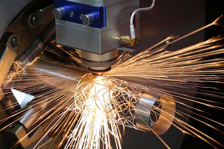
An IP54 enclosure rating is the starting point, not the solution. The real challenge is particulate ingress into the beam path protection windows and galvanometer cooling paths, combined with thermal stratification inside the machine frame when ambient temperature spikes from 5°C to 40°C during monsoon season. Thin-wall aluminum tube processing magnifies these effects because the material’s high reflectivity at 1060 nm forces the optics to handle substantial back-scattered energy, accelerating contamination buildup on the lens.
The optimal platform employs a pressurized optical chain with positive-differential nitrogen purge that maintains +0.3 bar inside the cutting head housing, actively preventing sub-micron dust from settling on the collimator. Sealed scanner housings with liquid-cooled galvanometer motors reject thermal drift, while an automatic nozzle-to-glass distance sensor with capacitive feedback detects protection window contamination and triggers an air-knife cleaning cycle. For aluminum, the assist gas circuit uses dynamic nitrogen pressure ramping from 14 to 20 bar to clear molten dross from the kerf without adding excessive heat. Back-reflection monitors operating at microsecond response thresholds protect the fiber coupling module, and the cutting head incorporates a replaceable sapphire window with anti-reflective coating rated for 2 kW CW, reducing replacement frequency in dusty bays.
Thermal Expansion Mitigation in the Optical Train and Machine Frame
Aluminum carries a thermal expansion coefficient of 23.1 µm/m·K. A 2-meter long X-axis beam constructed from mild steel grows roughly 0.024 mm per degree Celsius change. When the specification demands end-cut positional tolerance of ±0.1 mm on a 3-meter 6061-T6 tube with a 0.6 mm wall, a 2°C temperature gradient across the gantry turns a precision component into scrap. The best-in-class systems isolate the motion platform from thermal drift by employing composite granite machine beds or stress-relieved cast iron structures with integrated, balanced liquid cooling channels. The linear guide rails are installed with calculated preload to compensate for thermal elongation differential between the rail and the carriage block, preventing binding and position shift.
Distributed PT100 resistance temperature detectors embedded in the gantry, carriage, and base feed real-time data to a motion controller that adjusts the laser firing position using a digital twin model. This compensation algorithm predicts the thermal profile from measured gradients and corrects the scanner trajectory every millisecond, effectively neutralizing the frame’s expansion before it translates into a positional error. The fiber delivery cable itself demands management: a standard passively cooled 20-meter delivery fiber warms unevenly near the robot interface, altering the output beam diameter by as much as 4%. Active water-cooled jackets around the final 3 meters, combined with fiber routing that maintains a minimum bend radius of 200 mm, preserve the single-mode M² < 1.1 throughout the shift, keeping spot size and power density consistent on the tube surface.
Stress-Relieved Bed Stability: The Foundation No One Inspects
Machine builders often neglect to disclose the residual stress locked into their weld-fabricated frames. A welded steel bed that has not undergone thermal stress relief at 580°C will slowly relax over the first 400 operating hours, warping the linear rail mounting lands by 20–50 µm and introducing a permanent banana curve. For thin-wall aluminum tube processing, where a 0.05 mm gap inconsistency during cutting triggers variable kerf width and potential melt-through on the back wall of the tube, the bed must be dynamically inert. The highest-performing platforms utilize monolithic polymer-mineral castings with a density of 2.4 g/cm³ and a logarithmic decrement of 0.03—roughly ten times better vibration damping than grey cast iron. These structures are cast around precision-ground steel inserts and finish-lapped to within 5 µm flatness per meter, creating a stable reference plane that does not creep.
The machine bed is anchored via three-point kinematic mounts that decouple floor distortions, ensuring the entire system sits stress-free even if the facility’s concrete pad has settled unevenly. On a busy production floor, this isolation prevents transient vibrations from adjacent 200-ton stamping presses from transferring into the cutting point. Coupled with the granite-like thermal inertia of the casting, the bed maintains the coordinate system reference across shift changes, eliminating the need for morning recalibration after a cold night. Procurement teams that overlook this attribute will find their kerf wandering by 0.1 mm over a 6-meter tube length within a month of installation.
Specification Priorities Over Marketing Claims
Thin-wall aluminum tubular parts—HVAC manifolds, battery cooling tubes, lightweight structural members—demand a fiber laser platform that treats mechanical stability as a first-order design requirement, not an afterthought. Request from your supplier certified thermal mapping data of the machine frame under cyclic operation, dynamic laser interferometer plots showing positional stability under external vibration per ISO 230-2, and evidence of stress-relieved bed construction, including vibratory or thermal stress relief records. The best industrial fiber laser for thin wall aluminum tubes is not the one with the highest wattage, but the one that can maintain its geometry hour after hour when the shop bay door is left open in January.
Frequently Asked Questions
What laser power and beam quality are required for cutting thin-wall aluminum tubes without edge burrs?
A 1.5 kW to 2 kW single-mode fiber laser with M² < 1.1 is the sweet spot for wall thicknesses from 0.5 mm to 1.5 mm. Higher power increases the risk of runaway melt-through because aluminum’s thermal conductivity rapidly spreads heat, softening the surrounding parent material. A clean, oxide-free cut requires nitrogen assist gas at 14-18 bar with a nozzle standoff of 0.8-1.2 mm, combined with a tightly focused 25-50 µm spot size to minimize the heat-affected zone.
How does the machine bed design affect cut consistency on long aluminum tubes?
The machine bed directly governs positional accuracy over time. Weld-fabricated steel frames without stress relief will warp imperceptibly after the first few thermal cycles, causing the linear rails to deviate from straightness. This misalignment translates into a wandering beam that produces kerf width variations and part-length errors in tubes exceeding 2 meters. A polymer-mineral casting or stress-relieved, vibration-damped cast iron bed maintains geometric stability within 5 µm/m, ensuring the cut point stays on path despite ambient temperature swings and floor-borne vibrations.
What environmental factors cause fiber laser failures in tube processing cells, and how are they mitigated?
Three factors dominate: airborne particulate contamination from adjacent grinding or welding operations, condensation due to temperature/humidity swings, and vibration from nearby heavy stamping equipment. Mitigation requires more than an IP enclosure: positive-pressure optical path purging with dried, filtered air or nitrogen; automatic window contamination detection with capacitive monitoring; liquid-cooled galvanometer scanners that reject thermal lensing; and kinematic three-point machine mounting that isolates the bed from floor vibrations. Incorporating these features prevents the common shift-long drift that destroys cut quality on thin-walled aluminum tubes.


