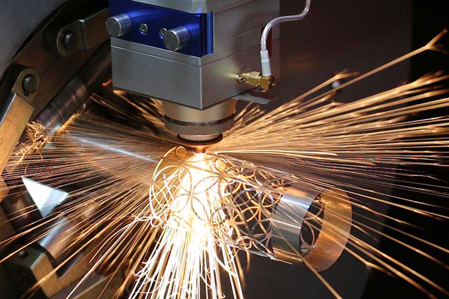
Optimizing Pneumatic Clamping and Rotary Synchronization for Thin‑Wall Structural Truss Beams
The fabrication of large structural steel trusses has moved decisively into single‑part‑flow digital manufacturing. Welded tubular nodes with compound bevels now require geometric tolerances that manual flame‑cutting and intermediate coping operations cannot sustain. At the core of this shift lies the need to produce full‑penetration weld preparations directly from solid models, with land thickness and root opening held within ±0.3 mm regardless of section geometry. The hardware that makes this possible is an integrated 5‑axis laser cutting cell, but its real‑world capability is governed less by the optical path than by the mechanical coupling between the workpiece and the motion system.
The structural steel truss supply chain increasingly demands zero‑gap nodal connections that require precise bevel profiles on rectangular and circular hollow sections. Fulfilling this requirement at production throughput forces fabricators to evaluate advanced machinery such as a 3D 5 axis tube laser beveling machine for structural steel trusses. While the laser source and 5‑axis head specifications dominate technical datasheets, the performance envelope is actually defined by three interdependent subsystems: pneumatic chuck clamping dynamics, rotary axis synchronization, and thin‑wall deformation control. The following analysis details how these elements interact and what design attributes separate a machine that holds process capability indices above 1.67 from one that generates scrap after the first few tubes.
Pneumatic Chuck Clamping Dynamics
Structural hollow sections present a bimodal D/t distribution: thin‑wall CHS chords may reach D/t ratios exceeding 65, while RHS branch members often land below 20. A single clamping strategy based on fixed hydraulic pressure will either plastically ovalize thin sections or slip during aggressive indexing of heavy profiles. The answer lies in closed‑loop pneumatic chucking with independent proportional pressure regulation for each jaw pair.
Each self‑centering chuck jaw incorporates a linear magnetostrictive position sensor that tracks clamp travel to within 5 µm. During the loading cycle, the CNC reads the jaw displacement signature and compares it against an internal look‑up table that correlates wall thickness, section shape, and material grade to the required preload. A proportional valve block, fed by a 10‑bar filtered air circuit, then ramps pressure to a target value calculated from the section’s second moment of area. This adaptive preload avoids the stick‑slip oscillations common to bang‑bang pneumatic circuits and prevents the dynamic friction drop that occurs when the laser heat input thermally expands the tube in the jaws. For thin‑wall CHS, the system can operate in a “soft‑touch” mode where clamping force is limited to 40 % of the elastic buckling threshold, then temporarily raised during high‑acceleration rapid moves by sniffing the trajectory planner’s velocity output.
The rotary union that supplies air to the chuck is integrated with a high‑speed slip ring, transmitting real‑time pressure and position data without twisted cables. Jaw inserts employ segmented carbide pads with a polyurethane backing layer that decouples bending moments, ensuring the tube’s neutral axis remains aligned with the spindle centreline. This design eliminates the secondary distortion that occurs when a purely metallic clamp imposes a lateral constraint incompatible with the residual stress state of the as‑rolled section.
Rotary Axis Synchronization
In a 5‑axis tube beveling process, the rotary A‑axis must track the path of the laser head with a synchronism error low enough to keep the land width constant around the entire intersection contour. Even a 0.02° lag during a rapid indexing move will produce a visible mismatch at the weld root. Achieving this on truss members up to 500 mm diameter and 12 m length, where the moment of inertia of the cantilevered tailstock end is enormous, requires a direct‑drive torque motor on the main spindle rather than a worm‑gear stage.
A frameless permanent‑magnet motor with a water‑cooled stator delivers a peak torque density above 800 N·m and is directly coupled to a 24‑bit absolute ring encoder. This gives a rotary position resolution of 0.0003° and, crucially, zero mechanical backlash. The servo loop for the A‑axis uses a third‑order jerk‑limited filter whose coefficients are dynamically modified by the CAM system based on the mass moment of inertia computed from the part program’s remaining stock length. Synchronization with the linear X, Y, Z axes and the tilting B/C axes is handled by a real‑time electronic cam table that compensates for the eccentricity and ovality measured during an initial 3D profilometer scan of the raw tube. The controller executes a forward‑looking contour algorithm that computes the deceleration profile required to stop the A‑axis at the exact angular position where the laser head initiates a pierce, eliminating overshoot burns on thin walls.
When processing a CHS rafter with an elliptical bracing intersection, the rotary axis must accelerate and decelerate asymmetrically because the projected intersection path traces a sinusoidal velocity profile. Standard trapezoidal velocity planning would induce cyclic torsional vibrations that show up as chatter marks on the bevel face. The solution is a gain‑scheduling velocity loop that measures actual acceleration through a MEMS accelerometer mounted on the chuck and adjusts the current command to the motor drive on a 16 µs cycle. This feedback mechanism masks the resonance of the cantilevered load and allows constant‑surface‑speed cutting, preserving the laser’s melt plume stability.
Thin‑Wall Deformation Control
Thermal expansion of thin‑wall sections during cutting is the dominant source of geometric error, far outweighing pure laser beam positioning uncertainty. A D/t ratio of 70 means that a temperature rise of just 150 °C in the heat‑affected zone can induce compressive yielding in the adjacent parent metal. The primary defense against this mechanism is a “floating tailstock” pneumatic steady rest that provides radial support while allowing unrestricted axial growth. The tailstock centre uses a hydrostatic air bearing that floats the tube with a stiffness of 120 N/µm, enough to counteract gravity sag but compliant enough to relieve thermal stress.
On the cutting side, the assist gas nozzle design is tuned to evacuate the melt without creating a pressure field that imparts a net force on the partially molten wall. A coaxial flow simulation, validated with Schlieren imaging during commissioning, defines the optimum stand‑off and pressure profile for the full D/t range. When the material is thinner than 3 mm, the machine switches to a high‑frequency pulsed regime (10 kHz, short duty cycle) that keeps the cumulative heat input below 60 J/mm², avoiding local buckling at the cut edge. The combination of adaptive clamping and controlled heat input reduces the need for post‑cut straightening and makes the as‑cut bevel acceptable for robot‑assisted welding without rework.
All three subsystems converge at the process monitoring layer. Real‑time torque feedback from the rotary axis serves as a proxy for workpiece slip, triggering an immediate clamp pressure ramp if the variation exceeds a pre‑defined slip threshold. Simultaneously, the beam path is re‑aligned using the live tube profile stored from the pre‑scan. This closed‑loop architecture allows the machine to run in a true “dark factory” mode for truss components, producing 45° compound bevels with land width tolerances of ±0.15 mm at rates exceeding 12 m/min, while safeguarding thin‑wall integrity from the first to the last part of the shift.
Technical Procurement FAQ
What wall thickness range can these machines handle without unacceptable distortion?
With adaptive pneumatic clamping and pulsed fiber laser control, well‑engineered 5‑axis tube lasers routinely process circular and rectangular hollow sections from 2 mm up to 20 mm wall thickness while maintaining profile tolerances of ±0.2 mm. Thin‑wall stability, especially on CHS with D/t greater than 50, relies on dynamic pressure profiling that references the CAD‑analyzed section moment of inertia and prevents plastic lobing at the chuck interface.
How does pneumatic chuck design affect cutting accuracy on thin‑wall tubes?
A self‑centering chuck with independent proportional pressure control per jaw pair avoids the plastic ovalization associated with fixed‑pressure hydraulic systems. Jaw travel feedback from linear sensors allows the controller to compute actual preload and adapt pressure during the cut cycle, maintaining sufficient torque transfer for indexing while reducing clamping force to a safe fraction of the buckling limit. Segmented insert materials decouple bending moments, keeping the tube axis aligned with the spindle centreline.
What synchronous control strategies minimize rotary axis lag during 5‑axis beveling?
Direct‑drive torque motors combined with 24‑bit absolute encoders eliminate mechanical backlash and provide sub‑arcminute positioning. The servo loop uses electronic camming informed by a live 3D profilometer scan of the tube, while jerk‑limited trajectory planning and gain‑scheduled velocity loops suppress torsional resonance of the cantilevered load. Real‑time accelerometer feedback ensures that the A‑axis tracking error stays below 0.01° even during asymmetric elliptical intersection cuts, preserving bevel land width consistency.













