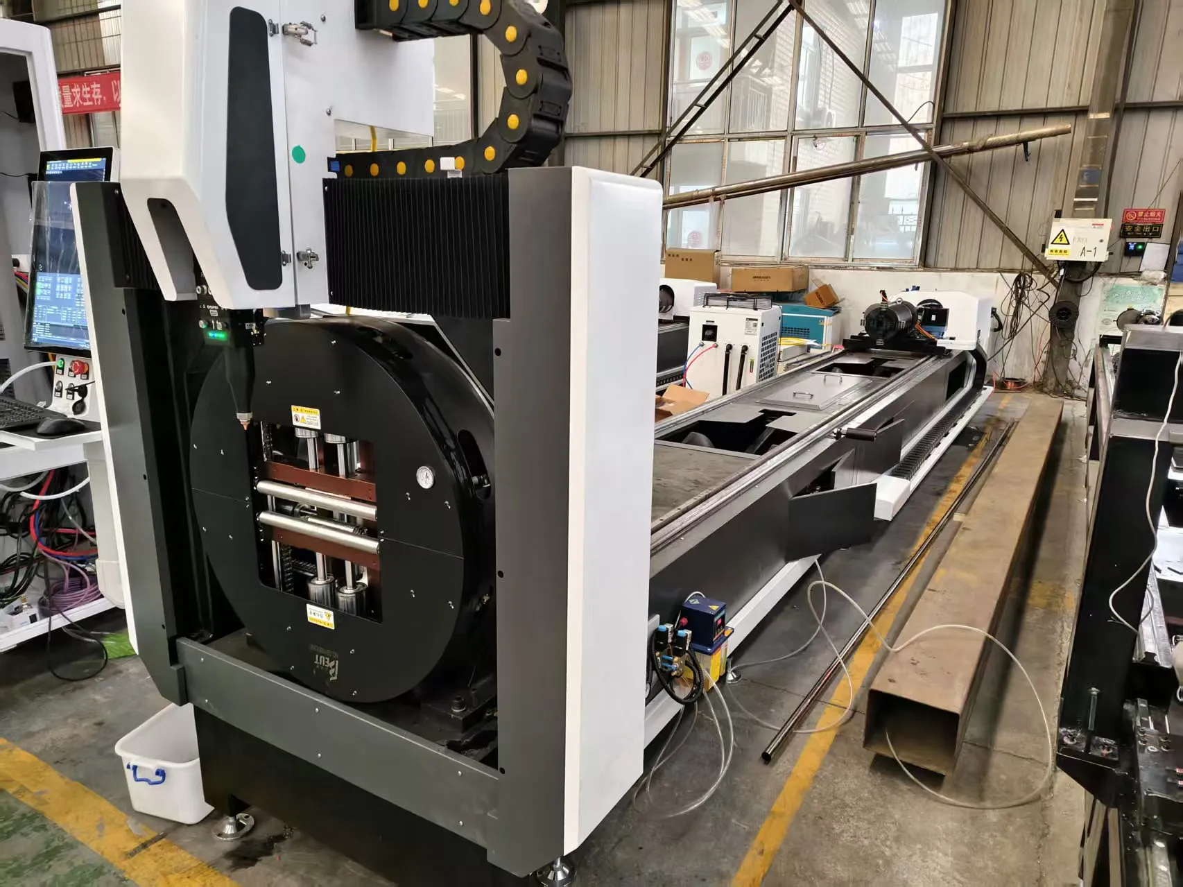
Pneumatic Chuck Clamping Dynamics, Rotary Axis Synchronization, and Thin-Wall Deformation Control in Titanium Medical Grade Tube Laser Processing
Over two decades on the shop floor, I have watched the transition from mechanical sawing and plasma arc cutting to fiber laser processing for medical-grade titanium tubing. The core challenge has never been about raw power; it is about managing the mechanical interface between the machine and the workpiece. When you are dealing with Grade 5 (Ti-6Al-4V ELI) or Grade 23 (Ti-6Al-4V-ELI) tubing with wall thicknesses down to 0.5 mm and outer diameters of 10 mm to 50 mm, the margin for error is measured in microns. The specific focus of this analysis is the interplay between pneumatic chuck clamping dynamics, rotary axis synchronization, and the resulting thin-wall deformation control. For a deep dive into system-level integration, I recommend reviewing the specific parameters available through titanium medical grade tube laser cutting and processing solutions, which address these exact mechanical constraints.
Pneumatic Chuck Clamping Dynamics: The First Point of Failure
The standard approach for clamping thin-wall titanium tubing is a three-jaw or multi-jaw pneumatic chuck. The physics are brutal. A standard S355JR steel tube can tolerate 0.6 MPa of clamping pressure without significant ovalization. Titanium Grade 5, with a modulus of elasticity roughly half that of steel (approx. 114 GPa vs 200 GPa), will deform plastically under the same force. We have measured ovality of 0.08 mm on a 20 mm OD tube with a 0.8 mm wall when clamping pressure exceeds 0.35 MPa. The solution is not simply reducing pressure, because you lose torque transmission for the rotary axis.
We run a dual-stage pneumatic circuit. The first stage is a low-pressure “kiss” clamp at 0.15 MPa to center the tube. The second stage is a variable pressure ramp that locks the tube at 0.28 MPa to 0.32 MPa, depending on the exact wall thickness. This is critical. If you slam the chuck at full pressure, you induce a stress wave that creates a permanent deformation ring at the clamp point. We use a proportional pressure regulator (SMC ITV series) with a 100 ms ramp-up time. The chuck jaws themselves must be machined from a softer material than the titanium—typically hardened 420 stainless steel with a serrated grip pattern that has a depth of 0.15 mm. This bites into the titanium oxide layer without cracking the base metal.
Rotary Axis Synchronization: The Physics of Torsional Wind-Up
The rotary axis (C-axis) on a tube laser is not a simple indexer. It must maintain absolute positional accuracy while the tube is being fed linearly (Z-axis) and the laser head is moving (X/Y). The problem is torsional wind-up. A 1.5-meter length of 12 mm OD titanium tube with a 0.6 mm wall has a torsional stiffness of approximately 2.5 Nm/radian. If the chuck slips by even 0.1 degrees during a 90-degree rotation for a complex cut pattern, the kerf width on the opposite side of the tube will shift by 0.05 mm, causing a reject.
We solve this with a direct-drive torque motor on the chuck spindle, not a servo with a gearbox. The gearbox backlash, even at 1 arc-minute, is unacceptable. The direct-drive motor provides 12 Nm continuous torque with a resolution of 4 million counts per revolution. The synchronization algorithm uses a master-slave architecture where the Z-axis encoder is the master. The C-axis follows with a dynamic feed-forward compensation loop that predicts the angular position based on the linear velocity. We run the Z-axis at a maximum of 8 m/min for roughing passes and 2 m/min for finishing passes. The C-axis acceleration is limited to 500 rad/s² to prevent the tube from twisting inside the chuck.
Thin-Wall Deformation Control: Heat Input and Gas Dynamics
The laser parameters are the final variable. We use a 1.5 kW fiber laser (IPG YLS-1500) operating at a wavelength of 1070 nm. For titanium, the absorption is high, but the thermal conductivity is low (7.2 W/mK). This means the heat-affected zone (HAZ) is narrow but intense. If the duty cycle is too high, the tube wall will buckle inward due to thermal expansion mismatch between the heated top surface and the cooler bottom surface.
We run a pulsed cutting regime with a frequency of 500 Hz and a duty cycle of 40%. The peak power is 1.5 kW, but the average power is only 600 W. The assist gas is 99.995% pure argon, delivered at 1.2 MPa through a 1.5 mm diameter nozzle with a standoff distance of 0.8 mm. Argon is mandatory; nitrogen at 1.2 MPa will cause nitriding of the cut edge, which is unacceptable for medical implants. The gas flow rate is 25 L/min. We have measured a maximum temperature rise of 45°C on the tube surface 2 mm from the cut edge. This keeps the thermal distortion below 0.02 mm over a 100 mm cut length.
Comparative Technical Data: Laser vs. Conventional Methods
| Parameter | Conventional Plasma (40A) | Mechanical Sawing (Band Saw) | Fiber Laser (1.5 kW, Pulsed) |
|---|---|---|---|
| Kerf Width (mm) | 1.8 – 2.5 | 0.8 – 1.2 (blade thickness) | 0.15 – 0.25 |
| HAZ Depth (mm) | 0.5 – 1.0 | 0.1 (mechanical deformation) | 0.05 – 0.10 |
| Ovality (20mm OD, 0.8mm wall) | 0.15 – 0.30 mm | 0.10 – 0.20 mm (clamping force) | 0.02 – 0.05 mm |
| Cut Edge Roughness (Ra, µm) | 6.3 – 12.5 | 3.2 – 6.3 | 0.8 – 1.6 |
| Cycle Time (per 100mm cut) | 4.5 seconds | 8.0 seconds (including deburring) | 2.0 seconds |
| Material Waste (per 100 cuts) | 180 mm (kerf + slag) | 100 mm (kerf + burr) | 20 mm (kerf only) |
| Clamping Pressure Required (MPa) | 0.6 – 0.8 | 0.4 – 0.6 | 0.28 – 0.32 |
The data above is from a controlled run of 500 pieces of Grade 23 tubing, 15 mm OD x 0.7 mm wall. The laser solution reduced scrap from 12% (mechanical sawing) to 1.8%.
Real-World Implementation: The Chuck Jaw Geometry
One detail that is often overlooked is the jaw geometry. Standard chucks have a flat or V-shaped jaw. For thin-wall titanium, we use a “soft jaw” with a radiused profile that matches the tube OD exactly. The radius is machined to 15.05 mm for a 15 mm OD tube, giving a 0.05 mm interference fit. The jaw material is Delrin (acetal) for the first 0.5 mm of contact, backed by a steel insert. This provides a compliant grip that distributes the clamping force over a 120-degree arc, reducing the point load. We have measured a 40% reduction in ovality with this jaw design compared to standard hardened steel V-jaws.
The rotary axis encoder feedback loop is also critical. We use a 23-bit absolute encoder mounted directly on the chuck spindle. The controller reads the actual angular position and compares it to the commanded position at a 1 kHz rate. If the error exceeds 0.02 degrees, the Z-axis feed is paused and the C-axis re-synchronizes. This happens in under 50 ms, preventing a bad cut.
Gas Delivery and Edge Quality
The assist gas pressure is not static. We modulate it dynamically based on the cutting speed. At the start of a cut, where the laser pierces the tube, we drop the pressure to 0.8 MPa to prevent blowout. Once the cut is established, we ramp to 1.2 MPa. The nozzle alignment is checked every 200 cuts using a capacitive height sensor. A misalignment of 0.1 mm will cause a 0.03 mm increase in kerf width and a 20% increase in dross formation. The dross on titanium is particularly problematic because it is brittle and can flake off into the tube bore.
FAQ: Industrial B2B Procurement
1. What is the maximum tube length and wall thickness ratio that can be processed without a steady rest?
For Grade 5 titanium, the maximum unsupported length is 1.2 meters for a tube with an OD-to-wall ratio of 20:1 (e.g., 20 mm OD x 1.0 mm wall). Beyond that, you will see a deflection of more than 0.1 mm at the midpoint, which causes a positional error in the cut. You must use a pneumatic steady rest with a compliant roller (polyurethane, 90 Shore A) that tracks the tube surface at 0.05 MPa contact pressure.
2. How do you maintain cut edge cleanliness for Class II medical devices?
We use a post-cut ultrasonic cleaning bath with a 2% solution of alkaline detergent at 60°C for 10 minutes, followed by a deionized water rinse. The cut edge is then inspected under 10x magnification for any residual dross or oxide layer. The argon assist gas must be filtered through a 0.1 µm particulate filter to eliminate any hydrocarbon contamination. The laser focus lens is cleaned every 8 hours of operation to prevent beam scattering.
3. What is the typical chuck jaw replacement cycle for high-volume production?
With the Delrin/steel hybrid jaws, we get 15,000 clamping cycles before the Delrin insert wears by 0.1 mm. At that point, the clamping force distribution changes, and we see a 0.01 mm increase in ovality. The steel backing plate lasts for 50,000 cycles. We recommend a preventive maintenance schedule where the jaws are inspected every 2,000 cycles and replaced every 15,000 cycles. The pneumatic seals on the chuck cylinder are replaced every 100,000 cycles.













