Process Inefficiencies in Structural Tube Finishing: A Systems-Level Analysis
Walking any fabrication floor handling H-beam or structural tube, the bottleneck rarely sits at the cutting nozzle. It sits at the grinding station, where operators spend 30% to 45% of their total cycle time removing slag, dross, and heat-affected zone (HAZ) inconsistencies left by plasma or oxy-fuel processes. When you are processing S355JR or S420MC with a wall thickness exceeding 12 mm, the secondary operation becomes a cost center that eats into your margin per ton. The shift toward how to reduce secondary grinding on H beam and structural tubes is not about buying a faster grinder; it is about eliminating the geometric and metallurgical conditions that necessitate grinding in the first place. This requires a hard look at your upstream material handling, the cutting physics, and how your machine communicates with your MES/ERP layer to enforce process stability.
Root Cause: Why Plasma and Sawing Create the Grinding Burden
Let’s quantify the problem. Conventional plasma cutting on structural profiles introduces a HAZ that can reach 1.5 to 2.0 mm in depth on S355JR. This hardened layer, combined with oxide buildup on the cut edge, requires aggressive mechanical removal before welding or painting. Similarly, cold sawing leaves a burr on the trailing edge of the cut—typically 0.3 to 0.8 mm—that must be manually deburred. The real issue is not the presence of these defects; it is their inconsistency. A plasma torch with worn electrodes or fluctuating gas pressure (below 0.6 MPa oxygen) produces erratic dross that adheres strongly to the bottom edge. Your grinder operators are not performing a finishing pass; they are performing a corrective machining operation on a part that has already deviated from tolerance.
The laser solution, specifically a 3D fiber laser tube cutting system, changes the physics. Using a 4 kW to 6 kW IPG or nLIGHT fiber source, you achieve a cut kerf of 0.3 mm with a HAZ under 0.1 mm. At this level, the dross is either absent or so thin (less than 0.05 mm) that it flakes off during the unloading process. But here is the critical engineering catch: the laser only delivers this clean cut if the beam is perfectly centered on the seam and the focus position is maintained within ±0.1 mm. This is where your upstream automation interfacing becomes the deciding factor between a clean part and a rework ticket.
Upstream/Downstream Automation: The Mechanical Prerequisite for Zero Grinding
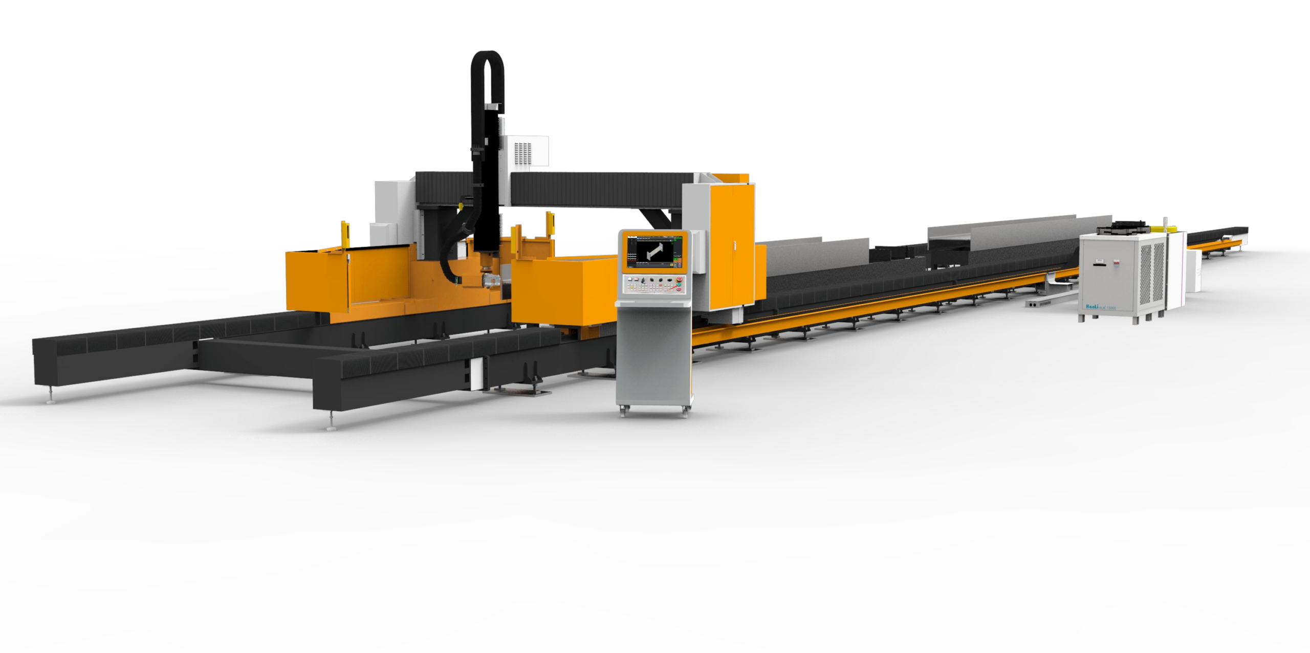
You cannot achieve a dross-free laser cut on an H-beam if the material is not presented to the chuck with absolute positional repeatability. The industry standard for this is an auto-bundling loader integrated with a servo-driven material staging conveyor. The loader must separate individual beams from the bundle without scratching the flange surface—because a scratch of 0.2 mm depth on the clamping area will cause the chuck to grip off-center, leading to a taper cut.
Specifically, your loader should use a magnetic separation system for ferritic steels (S235JR to S460NH) or a mechanical prying mechanism for stainless (SUS304) to avoid surface marring. The transfer arms must position the beam within ±1.0 mm of the chuck centerline. Once inside the chuck, the clamping pressure must be regulated precisely. For an H-beam with a 300 mm flange width, your pneumatic chuck should operate at 0.6 to 0.8 MPa, but you must use a pressure-reducing valve to drop to 0.4 MPa when cutting thin-walled tubes (t < 3 mm) to prevent ovalization. If the chuck deforms the profile by even 0.5 mm, the laser focus shifts, and you will see a striation pattern that requires grinding to smooth out.
Downstream, the cut part must be removed without collision. A drop-down part catcher with a soft polyurethane lining is non-negotiable. If the finished part falls onto a hard steel roller conveyor, the impact can create a burr on the cut edge—negating the entire benefit of the laser cut. The catcher should lower the part at a controlled rate of 0.2 m/s to avoid edge deformation.
MES/ERP Integration: Locking the Parameters to Kill Variability
Here is the analytical truth: manual parameter adjustment is the enemy of secondary grinding reduction. When an operator manually tweaks the laser power or cutting speed to “help” a difficult batch, they introduce variability. The solution is a closed-loop control system governed by your MES/ERP. The laser cutting machine’s CNC controller (typically Siemens 840D sl or Mitsubishi M800) must receive a work order from the MES that specifies not just the geometry, but the exact cutting recipe for that specific heat number of material.
For example, when processing S355JR with a 6 kW laser, your recipe for 10 mm wall thickness should dictate a cutting speed of 2.8 m/min, a nitrogen assist gas pressure of 1.2 MPa, and a focal position of -2.0 mm relative to the top surface. If the MES detects that the material certificate indicates a higher carbon equivalent (CEV > 0.45%), it must automatically adjust the cutting speed down to 2.4 m/min and increase the nitrogen pressure to 1.5 MPa to prevent hardening on the cut edge. This data exchange happens via OPC UA protocol, ensuring that the machine does not execute a cut without the explicit digital approval from the ERP. This eliminates the “trial and error” approach that leads to one bad cut out of ten, which then requires grinding to salvage.
Technical Comparison: Conventional vs. Fiber Laser for Structural Profiles
| Parameter | Conventional Plasma (Oxy-fuel mix) | Mechanical Sawing (Cold Saw) | 4kW-6kW Fiber Laser (Proposed) |
|---|---|---|---|
| Kerf Width (mm) | 3.0 – 5.0 | 2.0 – 4.0 (blade thickness) | 0.3 – 0.5 |
| HAZ Depth (mm) on S355JR | 1.5 – 2.5 | 0.5 (work hardening) | < 0.1 |
| Dross Adhesion (Bottom Edge) | High – requires chipping hammer & grinder | Burr formation 0.5mm | Negligible – breaks off during handling |
| Secondary Grinding Time (min/meter) | 4.5 – 6.0 | 2.0 – 3.0 | 0.0 – 0.2 (cosmetic only) |
| Cutting Speed (m/min) @ 10mm | 0.8 – 1.2 | 0.2 – 0.5 | 2.5 – 3.0 |
| Edge Squareness Tolerance | ± 2.0° (angular error) | ± 0.5° | ± 0.1° |
| Assist Gas Consumption | O2 @ 0.6-0.8 MPa (high consumption) | N/A (coolant) | N2 @ 1.2-1.5 MPa (pulsed) |
| Automation Interface (MES) | Rarely integrated | Manual loading | Full OPC UA / ERP integration |
The data above highlights a critical operational metric: the laser reduces secondary grinding time by over 95%. However, this is only achievable if the nitrogen purity is maintained at 99.99%. If your nitrogen supply drops to 99.5% purity (due to poor bulk tank management), the cut edge will oxidize and turn blue, creating a hard scale that requires grinding. Therefore, your facility must install an inline nitrogen purity monitor that alarms the MES if purity drops below 99.9%, triggering a halt in production rather than allowing defective parts to proceed.
Optimizing the Cutting Recipe for Specific Alloys
To truly eliminate grinding, you must adjust the laser duty cycle and pulse shaping. For structural steel (S355JR), a continuous wave (CW) laser mode is optimal. However, for aluminum (Al6061) or stainless (SUS304), you need a pulsed mode. For SUS304, use a frequency of 2,500 Hz with a duty cycle of 60% to prevent the formation of a viscous dross that sticks to the bottom edge. The pulse shaping must be set to a “ramp down” profile, where the power drops from 100% to 20% in the last 2 mm of the cut to blow out the molten material cleanly. If you use a constant power profile, the molten metal will re-solidify on the bottom edge, creating a “hanging” dross that requires manual removal.
Furthermore, the focus lens condition is paramount. A contaminated or scratched lens (typically a 5-inch focal length ZnSe lens) will scatter the beam, increasing the kerf width and causing striations. You must implement a lens condition monitoring system that tracks the back-reflection percentage. If the reflection exceeds 2% of the emitted power, the system must flag the lens for cleaning or replacement. This predictive maintenance step prevents the gradual degradation of cut quality that often leads to unexpected grinding requirements in the middle of a production run.
Implementation Blueprint for the Workshop Floor
Start by auditing your current bottleneck. If you are running a plasma table, measure the actual dross height on the bottom edge of a 12 mm H-beam. If it exceeds 1.0 mm, you are losing money on grinding media and labor. Transition to the fiber laser system with the following integration steps:
- Step 1: Install the auto-bundling loader with magnetic separation. Calibrate the positioning sensors to ensure the beam is squared to the chuck within 0.5 mm.
- Step 2: Configure the MES to send the “Cutting Recipe ID” via the OPC UA server. The recipe must include laser power, frequency, gas pressure, and focal position.
- Step 3: Set the nitrogen delivery pressure at the machine inlet to 1.5 MPa (with a 20% buffer above the 1.2 MPa required at the nozzle). Install a high-flow proportional valve to maintain pressure stability during rapid acceleration/deceleration of the cutting head.
- Step 4: Program the CNC to perform a “test cut” on a 50 mm scrap section at the start of every shift. The system measures the dross presence using a laser profilometer. If the dross height exceeds 0.1 mm, the machine automatically recalibrates the focus position before cutting the first production part.
By enforcing this digital and mechanical discipline, you shift your workforce from grinding operators to machine supervisors. The reduction in secondary grinding is not a hope; it is a calculated outcome of maintaining the laser’s focal point stability and the material’s positional accuracy. The return on investment is measured not just in labor hours saved, but in the elimination of rework scrap and the ability to quote tighter tolerances to your clients in the structural steel sector.
Frequently Asked Questions (B2B Procurement)
Q1: What is the minimum laser power required to cut H-beams up to 20 mm thick without secondary grinding?
For structural steel up to 20 mm, you need a minimum of 6 kW fiber laser. However, to ensure a dross-free bottom edge, you must also have a high-pressure nitrogen supply (up to 2.0 MPa at the source) and a cutting head with a 150 mm collimation lens. At 6 kW, you will cut 20 mm S355JR at approximately 1.8 m/min with a HAZ under 0.2 mm, which eliminates grinding requirements.
Q2: How does the auto-bundling loader interface with existing overhead crane logistics in a legacy workshop?
The loader is designed to integrate with your existing crane system via a handshake protocol. The crane drops the bundle onto a buffer table, and the loader uses laser distance sensors to map the bundle geometry. It then separates individual beams using a servo-driven prying arm, eliminating the need for crane operator precision. The MES system tracks the bundle ID and associates it with the cutting program, ensuring traceability from the yard to the finished part.
Q3: Can the MES/ERP integration retroactively adjust cutting parameters for material hardness variations within the same batch?
Yes. If your ERP has mill certificate data (including CEV and tensile strength), the MES can segment the batch. For example, if the first 5 beams have a CEV of 0.40 and the next 5 have a CEV of 0.48, the MES will automatically switch the cutting recipe between beams. This is achieved by writing a conditional logic script in the MES that monitors the beam sequence and adjusts the laser power output via the CNC’s analog interface.













