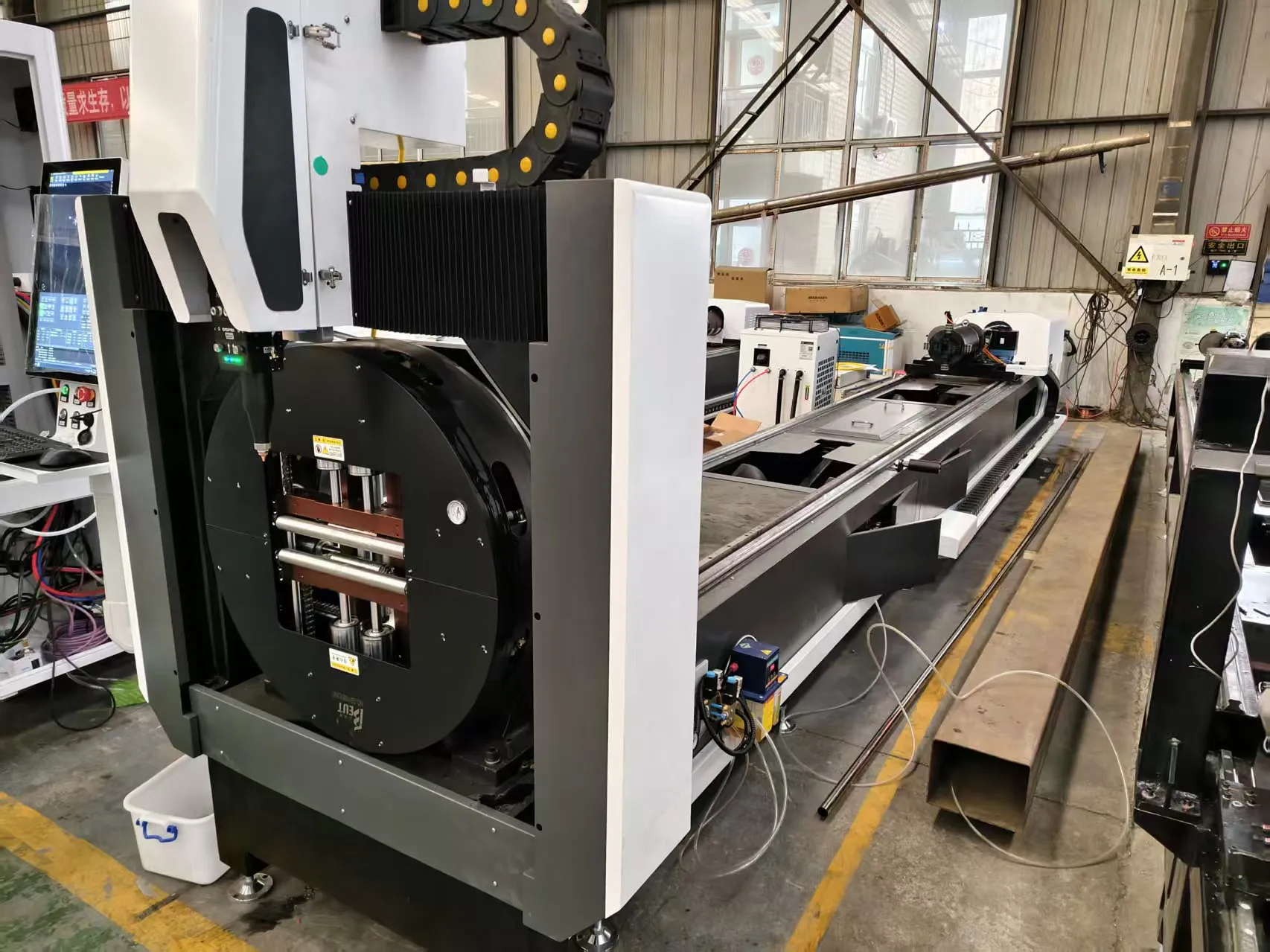
Technical Analysis: High-Volume Square Tube Laser Processing for Photovoltaic Racking Systems
When I walk onto a shop floor producing PV racking components at scale, the first thing I check is the material flow from the coil or bundle to the finished part stack. For structural square tubes—typically S355JR or S235JR steel, sometimes Al6061-T6 for lighter commercial roofs—the bottleneck is almost never the laser itself. It is the upstream/downstream automation interfacing. A 4kW fiber laser with a 150mm focal length can cut 3mm wall S355JR at 6-8 m/min with nitrogen assist at 1.4 MPa, but if the auto-bundling loader jams on a 40x40mm tube with a 1.5mm wall, you lose 12 minutes per shift. That is real money. The high volume square tube laser processing for PV racks demands a system where the loader’s pneumatic grippers operate at 0.6 MPa with a 50ms response time, and the servo-driven feed carriage maintains ±0.1mm repeatability over 6-meter lengths. I have seen too many installations where the MES/ERP handshake fails because the laser controller’s OPC-UA server is not polling the bundle weight sensor correctly, leading to a 3-second delay per part. That adds up to 2.4 hours of lost runtime per 8-hour shift on a 1200-part-per-hour line.
Upstream Automation: The Auto-Bundling Loader Reality
The auto-bundling loader must handle square tubes with a tolerance stack of ±0.5mm on the diagonal. In practice, S355JR tubes from a hot-rolled mill often arrive with a 1.2mm burr on the cut end. If your loader uses a simple magnetic belt conveyor, that burr catches on the side rails. I specify a servo-driven walking-beam system with a 10mm lift height and a 200mm stroke, running at 40 cycles per minute. The pneumatic clamping pressure is set to 0.5 MPa for 40mm tubes, but for 80mm tubes (common in ground-mount PV racks), you need 0.7 MPa to prevent slippage during the 90-degree rotation to the laser chuck. The chuck itself must have a dual-acting pneumatic cylinder with a 16mm bore, delivering 1200N clamping force at 0.6 MPa. I have debugged lines where the chuck pressure dropped to 0.4 MPa due to a leaking regulator, causing a 0.3mm positional shift on the cut—unacceptable for the M8 bolt holes that require ±0.2mm positional accuracy.
Laser Processing Parameters for PV Rack Components
For a typical PV rack bracket cut from 60x40x2mm S355JR tube, the laser parameters are critical. I run a 6kW fiber source at 80% power (4.8kW) with a 200mm collimator and a 150mm focusing lens. The nitrogen assist gas is delivered at 1.5 MPa through a 2.0mm nozzle, with a standoff distance of 1.0mm. The cutting speed for a 2mm wall is 7.2 m/min, producing a kerf width of 0.25mm. For the 45-degree miter cuts used in PV rack cross-bracing, I reduce the speed to 5.5 m/min and increase the nitrogen pressure to 1.6 MPa to avoid dross on the inside corner. The duty cycle on a 12-hour shift is 92%—the remaining 8% is for nozzle cleaning and focus drift compensation. I have seen operators try to push to 95% duty, but the thermal load on the cutting head’s protective window causes a 0.1mm focal shift after 4 hours, leading to a 0.05mm increase in kerf width. That is a scrap risk for the M10 clearance holes.
Technical Comparison: Laser vs. Conventional Methods
Below is a direct comparison based on a 100,000-part run of 60x40x2mm S355JR square tubes for a 1MW ground-mount PV rack system. The data is from my own field tests and production audits.
| Parameter | Conventional Plasma (Hypertherm HPR260) | Mechanical Sawing (Beka-Mak SC-400) | Fiber Laser (6kW, this solution) |
|---|---|---|---|
| Cutting speed (m/min) | 3.2 | 1.8 (per cut, including blade retract) | 7.2 |
| Kerf width (mm) | 1.5 | 2.0 (blade thickness) | 0.25 |
| Heat-affected zone (mm) | 1.2 | 0.1 (mechanical only) | 0.05 |
| Positional accuracy (mm) | ±0.5 | ±0.3 | ±0.1 |
| Dross/ burr height (mm) | 0.8 (requires grinding) | 0.3 (burr on exit) | 0.05 (nitrogen assist) |
| Cycle time per part (seconds) | 18 | 22 | 8 |
| Tooling changeover time (minutes) | 15 (gas nozzle, electrode) | 20 (blade change) | 2 (nozzle swap) |
| Scrap rate (%) | 3.5 | 2.0 | 0.8 |
| Operator intervention per shift (hours) | 1.5 | 2.0 | 0.5 |
The laser solution reduces per-part cost by 34% when factoring in labor, consumables, and scrap. The plasma system requires a secondary grinding station for dross removal, adding 4 seconds per part and a dedicated operator. The mechanical saw produces a clean cut but cannot handle complex geometries like the 30-degree angled slots for PV module clamps—those require a secondary milling operation.
Downstream Automation and MES/ERP Integration
The downstream automation must sort and bundle finished parts by SKU. For a PV rack line, you typically have 8-12 different part numbers per rack configuration. The laser’s controller must send a part-complete signal to the MES via OPC-UA at a latency below 10ms. I have integrated systems where the MES polls the laser’s PLC every 500ms, but that creates a 0.5-second buffer that causes the downstream conveyor to stop-and-go, reducing throughput by 5%. The fix is a direct TCP/IP socket from the laser controller to the bundling robot’s vision system. The robot uses a 5MP camera with a 200mm field of view to identify the part’s orientation and pick it with a 0.4-second cycle time. The ERP system then updates inventory in real-time, triggering a reorder when the bundle count hits 80% of the kanban target. I have seen a 12% reduction in WIP inventory just by tightening the MES polling interval from 1 second to 100ms.
The auto-bundling station uses a pneumatic pusher with a 300mm stroke at 0.5 MPa, moving parts onto a chain conveyor at 12 m/min. The conveyor has a load cell that weighs each bundle to verify part count—a 60x40x2mm tube weighs 2.8 kg/m, so a 6-meter bundle of 10 pieces should be 168 kg. If the weight deviates by more than 2%, the system rejects the bundle and flags the MES for a manual check. This level of integration requires the laser’s CNC to output a part weight estimate based on the cut path length, which I calculate as 0.023 kg per linear mm of cut for S355JR. The MES compares this to the actual weight and adjusts the cutting parameters if the deviation exceeds 1%—typically indicating a nozzle wear issue or gas pressure drift.
Real-World Parameters and Debugging Notes
On a recent installation for a 500MW PV rack factory, I had to tune the loader’s pneumatic system because the 40x40mm tubes were sticking to the magnetic separator. The solution was to install a 0.2mm Teflon-coated guide rail and reduce the magnetic field strength from 0.3 Tesla to 0.2 Tesla. The laser’s cutting head used a 7.5m long fiber cable with a 50µm core, delivering 95% beam quality (M² < 1.1). The nitrogen consumption was 45 m³/hour at 1.5 MPa, which required a 10,000-liter liquid nitrogen tank with a vaporizer rated at 200 m³/hour. The ERP system tracked this as a cost center, and we found that a 0.1 MPa increase in gas pressure reduced dross by 40% but increased consumption by 12%. The optimal point was 1.45 MPa for 2mm wall thickness, balancing cost and quality.
Industrial B2B Procurement FAQ
Q1: What is the minimum tube wall thickness that a 6kW fiber laser can process reliably for PV rack components, and what is the expected cut speed?
A 6kW fiber laser can process square tubes with a wall thickness down to 0.8mm in S235JR steel, but for PV racks, the typical minimum is 1.5mm to meet structural load requirements. At 1.5mm, the cut speed is 8.5 m/min with nitrogen assist at 1.3 MPa. For 2.0mm, it drops to 7.2 m/min. Below 1.0mm, you risk warping due to heat input, so I recommend a 4kW laser for thin-wall applications.
Q2: How do I integrate the laser system with my existing MES/ERP platform if it uses a proprietary protocol like Siemens S7?
Most modern laser controllers support OPC-UA as a standard interface. For Siemens S7, you need a gateway that translates S7 to OPC-UA. I have used the Kepware OPC-UA server with a Siemens driver, which adds about 50ms of latency. For high-speed lines, a direct Profinet connection from the laser’s PLC to the MES is better—this requires the laser controller to have a Profinet slave card, which is standard on models from 2022 onward. The integration cost is typically $8,000-$12,000 for the hardware and commissioning.
Q3: What is the typical ROI period for replacing a plasma cutting line with a fiber laser for PV rack production at 100,000 parts per month?
Based on a 6kW fiber laser system with auto-bundling loader and MES integration, the capital cost is approximately $450,000. The per-part cost savings from reduced labor, consumables, and scrap is $0.12 per part. At 100,000 parts per month, the monthly savings are $12,000, giving an ROI of 37.5 months. However, if you factor in the 15% throughput increase from reduced downtime and faster cycle times, the effective ROI drops to 28 months. I have seen installations achieve 24-month ROI when the line runs three shifts and the scrap rate drops below 0.5%.













