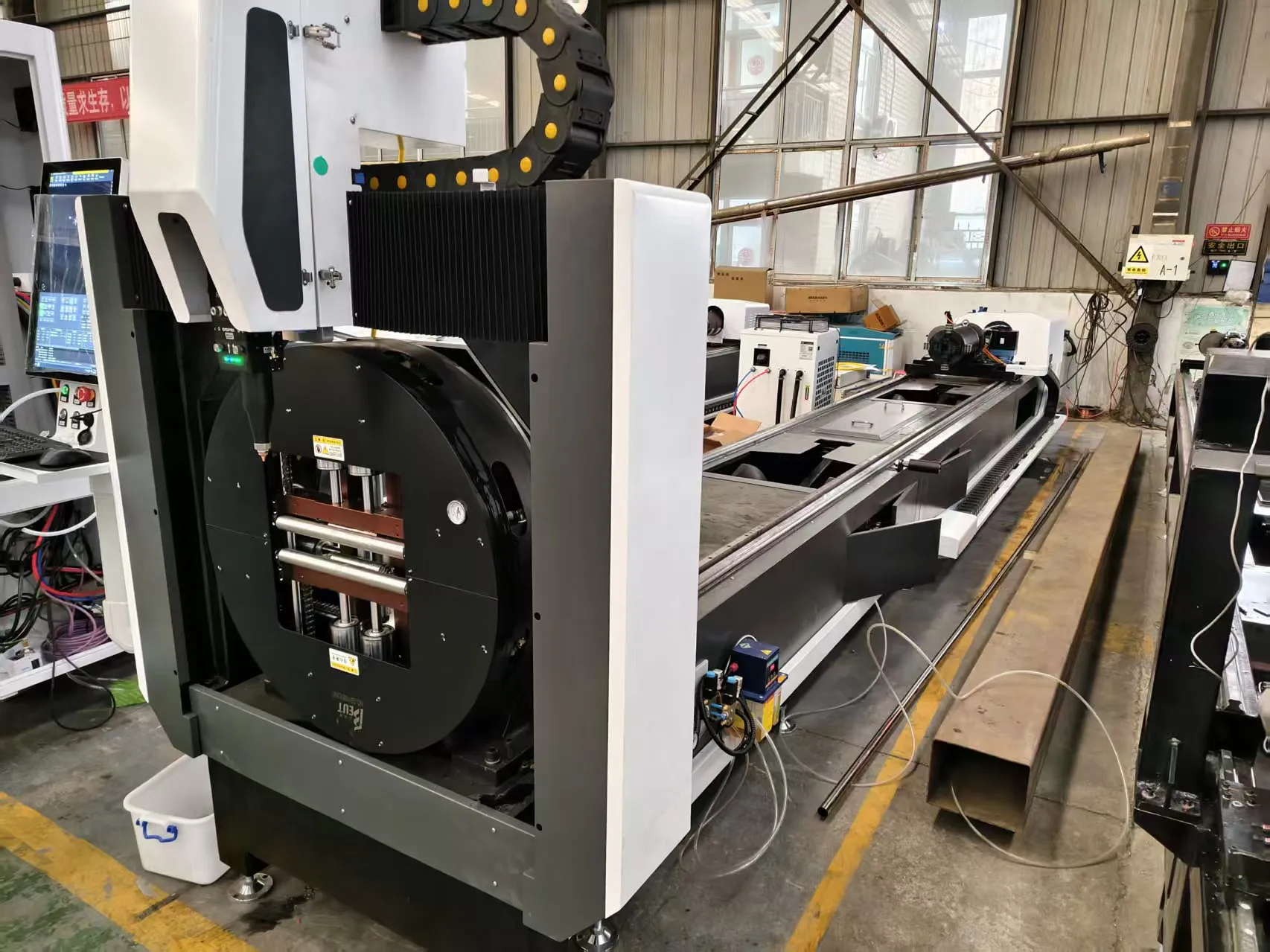
Process Metallurgy and System Architecture for Thick-Wall Tube Cutting
Cutting 20mm thick structural steel pipe with a fiber laser is not a scaled-up version of 3mm sheet work. The physics change entirely once the wall thickness exceeds roughly 12mm. At 20mm on S355JR or SUS304, the kerf no longer behaves as a thin slit — it becomes a deep, narrow melt channel where assist gas dynamics, Rayleigh length stability, and heat accumulation dictate whether you get a dross-free edge or a scrapped tube. For shops running a high power fiber laser for 20mm thick structural steel pipes, the bottleneck is rarely the resonator. It is the material handling interface: the chuck, the rotary axis, and the tube itself.
This paper focuses on the three failure modes we see most often on the floor: pneumatic chuck clamping dynamics, rotary axis synchronization errors, and thin-wall deformation control on long-span structural tubes.
Resonator Selection and Beam Delivery Constraints
For 20mm carbon steel, a 12kW to 20kW source is the practical entry point. Below 10kW, the cutting speed on S355JR drops to a point where the heat-affected zone (HAZ) widens past 0.4mm and oxidation dross becomes unavoidable at the bottom edge. Typical production parameters for 20mm S355JR with nitrogen assist:
- Laser power: 12,000 W to 15,000 W
- Frequency: 1,200 Hz to 1,800 Hz (modulated for edge quality)
- Duty cycle: 85% to 92% continuous
- Focal position: -4mm to -6mm below surface
- Nitrogen pressure: 1.2 MPa to 1.5 MPa at the nozzle
- Nozzle standoff: 0.8mm to 1.2mm
- Cutting speed: 0.9 m/min to 1.4 m/min
For SUS304 at 20mm, oxygen assist at 0.5 MPa to 0.8 MPa is often preferred for speed, but the oxide layer requires post-processing. Al6061 at 20mm is rarely cut with a fiber laser at this thickness due to reflectivity and dross adhesion — most shops still route it to a saw.
Pneumatic Chuck Clamping Dynamics
The chuck is where most 20mm tube jobs fail. A 20mm wall pipe weighing 180 kg to 400 kg per 6-meter length generates significant radial and axial loads during acceleration. Pneumatic chucks typically operate between 0.5 MPa and 0.8 MPa clamping pressure. Below 0.5 MPa, jaw slip occurs during rapid rotary indexing. Above 0.9 MPa on thin-wall tubes, you crush the profile.
Key field observations:
- Jaw contact area must be matched to tube OD. A 4-jaw scroll chuck with 60mm wide contact pads distributes load better than 3-jaw configurations on structural pipe.
- Clamping pressure should be staged: 0.3 MPa for initial centering, then ramp to 0.6 MPa to 0.7 MPa for cutting.
- Chuck runout must stay under 0.05mm TIR. Beyond that, the focal spot walks off the kerf centerline and dross forms on one side.
- Air supply must be dried to -40°C dew point. Moisture in the pneumatic circuit causes jaw pressure drift of 0.05 MPa to 0.1 MPa over a shift, enough to lose grip on a 400 kg tube.
Rotary Axis Synchronization
On a 6-meter tube, the rotary axis and the linear X-axis must stay synchronized within 0.02mm over the full travel. Servo mismatch beyond this produces taper on the cut face and, on 20mm wall, visible stair-stepping. The rotary axis encoder resolution should be at least 20 arc-seconds. Belt-driven rotary axes are inadequate for this thickness — direct-drive or dual-pinion gearboxes are mandatory.
Thermal drift is the silent killer. After 90 minutes of continuous cutting at 12kW, the chuck body expands 0.03mm to 0.08mm depending on ambient temperature. Shops running 24-hour production should re-zero the rotary axis every 4 hours or use closed-loop thermal compensation.
Thin-Wall Deformation Control
Structural pipe at 20mm wall is not thin-wall in the classical sense, but long spans sag. A 6-meter tube supported only at the chuck and tailstock deflects 0.5mm to 1.2mm at mid-span under its own weight. This deflection changes the focal standoff and produces inconsistent kerf width. Solutions:
- Add a steady rest at mid-span for tubes over 4 meters.
- Use a follow-rest synchronized to the cutting head position.
- Reduce cutting speed by 15% on unsupported spans to compensate for focal drift.
Comparative Technical Data: Legacy vs. High Power Fiber Laser
| Parameter | Plasma Cutting | Mechanical Sawing | 12kW Fiber Laser (20mm S355JR) |
|---|---|---|---|
| Cut speed (20mm wall) | 0.6 m/min | 0.15 m/min | 1.1 m/min |
| Kerf width | 3.5mm to 5.0mm | 4.0mm to 6.0mm | 0.8mm to 1.2mm |
| HAZ width | 1.5mm to 2.5mm | 0.2mm (mechanical) | 0.25mm to 0.4mm |
| Edge squareness | ±1.5° | ±0.5° | ±0.2° |
| Dross / burr | Heavy, requires grinding | Burr on exit side | Minimal with N2 assist |
| Setup time per tube | 8 to 15 min | 5 to 10 min | 2 to 4 min |
| Consumable cost / meter | High (electrodes, nozzles) | Blade wear | Nozzle + lens only |
| Automation compatibility | Limited | Low | Full (chuck + rotary + nesting) |
Gas Delivery and Nozzle Geometry
At 20mm thickness, the assist gas must maintain pressure through a 20mm deep kerf. A single nozzle at 1.5 MPa with a 2.0mm orifice is the baseline. Double-flow nozzles improve dross removal on SUS304 but add 0.2 MPa to 0.3 MPa of back-pressure. Oxygen cutting on carbon steel at this thickness runs 0.5 MPa to 0.8 MPa with a larger orifice (2.5mm to 3.0mm) to sustain the exothermic reaction.
Procurement FAQ
What laser power is required to cut 20mm structural steel pipe cleanly?
A minimum of 12kW is required for S355JR at production speeds. For SUS304 or thicker walls above 22mm, 15kW to 20kW is recommended to maintain edge quality and avoid dross.
How does pneumatic chuck pressure affect cut quality on thick-wall tubes?
Clamping pressure between 0.5 MPa and 0.8 MPa is optimal. Below 0.5 MPa, jaw slip causes rotary misalignment and taper. Above 0.9 MPa, thin-wall or large-diameter tubes deform, which shifts the focal standoff and produces inconsistent kerf width.
Can a fiber laser replace plasma and sawing for 20mm pipe in a production environment?
Yes, for carbon steel and stainless. A 12kW fiber laser delivers 1.1 m/min on 20mm S355JR with a 0.8mm to 1.2mm kerf, versus 0.6 m/min for plasma and 0.15 m/min for sawing. The trade-off is higher capital cost and stricter requirements on chuck runout and rotary synchronization.













