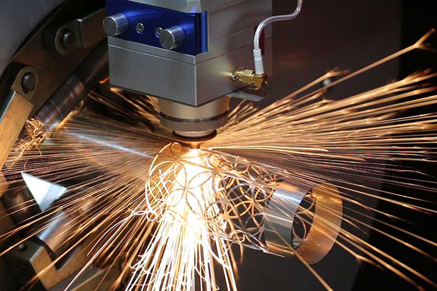
System Dynamics and Metallurgical Constraints in Thick-Wall Tubular Processing
Fabricating API 5L X70 or X80 line pipe and high-collapse casing for downhole oilfield service demands a departure from standard structural tube processing. When wall thickness exceeds 12 mm and outer diameters push past 508 mm (20 inches), the thermal mass of the workpiece dictates every machine parameter. A standard 3 kW CO2 or entry-level fiber system cannot maintain a stable kerf. The physics require a heavy obligation tube laser for oilfield pipeline fabrication that integrates a 12 kW to 20 kW IPG or nLIGHT source with a gantry-style, double-chuck architecture. This configuration is not a luxury; it is a mechanical necessity to counteract the gravitational sag and rotational inertia of a 1,200 kg tubular section.
Field data from Gulf Coast fabrication yards indicates that mechanical sawing of 25 mm wall S355JR introduces a heat-affected zone (HAZ) of 2.5 to 4.0 mm, requiring subsequent milling for weld bevels. Plasma cutting on 316L stainless creates a nitride-contaminated dross layer that demands grinding before GTAW root passes. The fiber laser, operating at 1,070 nm wavelength with a beam parameter product (BPP) of 2.5 to 4.0 mm·mrad, delivers a focused spot diameter of 180 to 250 µm. This energy density—exceeding 10^6 W/cm²—vaporizes the melt pool before significant lateral heat conduction occurs, reducing the HAZ to 0.3 to 0.8 mm on carbon steel and eliminating oxide inclusion on stainless grades.
Chuck Synchronization and Pneumatic Clamping Pressures
Rotating a 20-inch OD, 25 mm wall pipe at 60 RPM generates a tangential velocity of 1.6 m/s at the surface. The front and rear chucks must maintain angular synchronization within 0.02 degrees to prevent the beam from drifting off the cut path. This is achieved through a dual-servo, master-slave control loop with a 1 kHz update rate. Pneumatic clamping pressure for the collet jaws is typically set between 0.6 and 0.9 MPa for thin-wall, but escalates to 1.4 to 1.8 MPa for heavy-wall oilfield tubulars. Exceeding 2.0 MPa risks ovalizing the pipe; dropping below 1.2 MPa allows micro-slippage during rapid indexing, which introduces taper into the kerf.
Assist gas dynamics are equally critical. For 316L stainless and Inconel 625, high-pressure nitrogen at 1.2 to 1.5 MPa with a purity of 99.999% is mandatory to suppress chromium carbide precipitation. For carbon steel grades like API 5L X65, oxygen assist at 0.8 to 1.0 MPa accelerates the exothermic reaction, but the oxygen flow must be pulsed in sync with the laser duty cycle—typically 80% duty at 5 kHz modulation—to prevent uncontrolled burning at the kerf edges.
Advanced Nesting Software Algorithms and Common-Line Cutting Strategy
The material yield problem in oilfield pipeline fabrication is not a simple 2D nesting exercise. It is a 3D rotational nesting problem where the cut path wraps around a cylindrical surface. Modern CAM suites for heavy obligation tube lasers employ a genetic algorithm that evaluates thousands of cut-path permutations per meter of pipe. The objective function minimizes three variables: total cut length, rapid traverse distance, and the number of pierce points.
Common-line cutting is the single most impactful strategy for yield maximization. When two adjacent parts share a coincident edge—such as a 45-degree miter on a brace and a matching miter on a chord—the laser cuts a single kerf that serves both parts. This eliminates one pierce, one cut path, and the associated gas consumption. On a typical 12-meter joint of 24-inch pipe, common-line nesting can reduce total cut length by 18 to 24% and pierce count by 30%. The trade-off is a slight increase in kerf taper on the shared edge, which is acceptable for non-critical structural welds but requires compensation on API 5CT coupling stock.
Dynamic nesting algorithms also account for the “drop” or remnant section. After cutting the primary parts, the software evaluates whether the remaining 1.5 to 2.0 meters of pipe can accommodate smaller components—flanges, gussets, or thread protectors. This remnant utilization can push overall material yield from 78% to 91% on a per-joint basis.
Comparative Technical Data: Legacy Methods vs. Heavy Obligation Fiber Laser
| Parameter | Mechanical Sawing | Conventional Plasma | Heavy Obligation Fiber Laser |
|---|---|---|---|
| Max Wall Thickness (Carbon Steel) | 40 mm | 25 mm | 30 mm (single pass, 20 kW) |
| HAZ Width (S355JR, 20 mm wall) | 3.5–5.0 mm | 2.0–3.5 mm | 0.4–0.8 mm |
| Cut Edge Perpendicularity | ±0.5 mm (requires milling) | ±1.2 mm | ±0.15 mm |
| Nitrogen Consumption (per 12 m joint) | N/A | N/A (uses shop air) | 18–22 m³ at 1.4 MPa |
| Pierce Time (25 mm S355JR) | N/A | 2.5–4.0 s | 0.8–1.2 s |
| Typical Nesting Yield (per joint) | 72–78% | 75–80% | 88–93% with common-line |
| Post-Cut Finishing Required | Yes (milling, deburring) | Yes (grinding dross) | Minimal (wire brush) |
Material Yield Maximization Through Kerf Compensation and Skeleton Management
Kerf width on a 20 kW fiber laser cutting 25 mm carbon steel with nitrogen assist is typically 0.8 to 1.2 mm. The nesting software must apply a compensation offset of half the kerf width to every contour. Failure to do so results in dimensional drift of 0.4 to 0.6 mm per part, which accumulates across a nested array. For API 5L pipe with a ±1% wall thickness tolerance, this drift is unacceptable.
Skeleton management is the second lever. After the primary parts are cut, the remaining skeleton—the interconnected web of pipe wall—must be rigid enough to prevent the cut parts from shifting. The software inserts micro-tabs (0.5 to 1.0 mm wide) at strategic points along the contour. These tabs hold the part in place until the final pass, preventing the part from dropping into the pipe bore and jamming the chuck. The tab break-off force is calculated based on the material thickness and the part mass; for a 15 kg flange, a single 0.8 mm tab on S355JR requires approximately 120 N to fracture, which is well within the manual removal range.
For Al6061-T6 oilfield skid components, the nesting strategy shifts. Aluminum’s high reflectivity at 1,070 nm demands a higher peak power and a lower duty cycle—typically 60% at 3 kHz—to overcome the initial reflectivity barrier. The kerf is wider (1.5 to 2.0 mm) due to the material’s thermal conductivity, and the common-line strategy must be abandoned in favor of a 0.3 mm gap between parts to prevent weld-back.
Procurement FAQ for Heavy Obligation Tube Laser Systems
What is the minimum laser power required to cut 25 mm wall API 5L X70 pipe in a single pass?
For a single-pass cut on 25 mm carbon steel with a clean kerf and minimal dross, a 12 kW fiber laser is the absolute minimum. However, for production environments where cut speed and edge quality are non-negotiable, a 15 kW to 20 kW source is recommended. The 20 kW system can achieve 1.8 to 2.2 m/min on 25 mm S355JR with nitrogen assist at 1.4 MPa, whereas a 12 kW system drops to 0.9 to 1.1 m/min and may require oxygen assist, which introduces an oxide layer.
How does common-line cutting affect the dimensional tolerance of the final part?
Common-line cutting introduces a shared kerf that is typically 0.1 to 0.2 mm wider than a single-part kerf due to the dual-sided thermal load. This results in a tolerance shift of ±0.15 mm on the shared edge. For structural oilfield components (skids, frames, walkways), this is within acceptable limits. For API 5CT coupling stock or thread-critical components, common-line cutting should be disabled, and a 0.5 mm gap should be maintained between parts to preserve ±0.05 mm tolerance.
What pneumatic clamping pressure is required for a 1,200 kg, 20-inch OD pipe during high-speed rotation?
The required clamping pressure is a function of the pipe mass, the coefficient of friction between the collet jaws and the pipe surface, and the rotational acceleration. For a 1,200 kg pipe with a surface finish of Ra 3.2 µm, a minimum of 1.4 MPa is required to prevent slippage during a 0.5 second acceleration to 60 RPM. For pipes with mill scale or surface rust (Ra 12.5 µm), the pressure can be reduced to 1.1 MPa. Exceeding 1.8 MPa on thin-wall pipe (under 12 mm) risks plastic deformation of the pipe ends.













