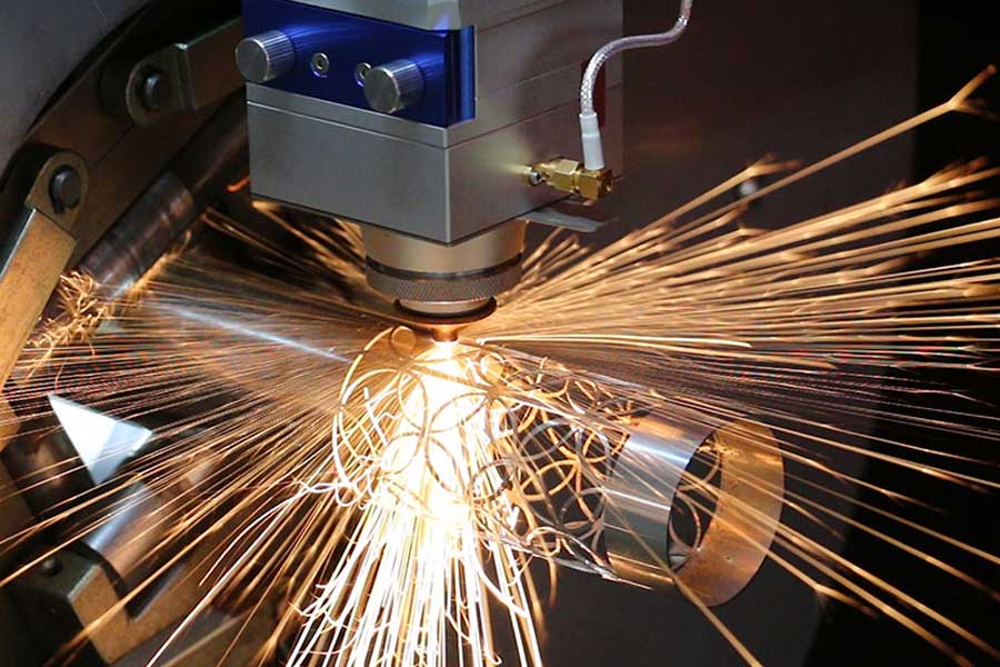
Tube Geometry Constraints in Railway Seat Frame Fabrication
Railway passenger seat frames are not simple rectangular weldments. A typical EN 15227-compliant frame assembly uses a mix of S355JR structural steel tube (wall thickness 2.5–4.0 mm), SUS304 stainless for grab-handle and armrest interfaces, and Al6061-T6 for weight-critical backrest pivots. The joint architecture almost always demands a beveled tube end: 30° to 45° single-bevel for butt welds, compound bevels where a curved backrest tube meets a straight seat pan rail, and saddle cuts where a smaller tube lands perpendicular on a larger one. The weld gap tolerance on these joints is typically ±0.15 mm; exceed it and you get lack-of-fusion defects that fail EN ISO 15614 procedure qualification.
This is exactly the class of work where a CNC tube beveling laser cutter for railway passenger seat frames stops being a luxury and becomes a process-control necessity. The machine does not just cut a profile — it establishes the weld-prep geometry that every downstream MIG or TIG pass depends on.
Why Conventional Methods Fail on Beveled Tube Joints
Mechanical sawing produces a flat 90° cut. To get a bevel you either add a secondary chamfering operation or accept a square-edge butt joint with poor penetration. Plasma cutting on thin-wall tube introduces a heat-affected zone of 0.8–1.5 mm, dross on the inner diameter, and a kerf taper of 3–7° that destroys the fit-up on a compound saddle. The dimensional repeatability across a batch of 200 seat frames is simply not there.
Fiber laser tube cutting with a beveling head changes the physics. A 3 kW single-mode source running 1,080 nm wavelength, focused to a 0.08–0.12 mm spot, cuts S355JR at 2.5 mm wall with nitrogen assist at 1.4 MPa and achieves a kerf width of roughly 0.15 mm with a perpendicularity deviation under 0.5°. When the cutting head tilts to 45° for the bevel, the same parameters hold — because the beam quality (M² < 1.3) keeps the focus stable through the tilt axis.
| Parameter / Method | Mechanical Saw + Chamfer | Plasma Tube Cutting | CNC Fiber Laser Beveling |
|---|---|---|---|
| Bevel angle capability | Fixed 45° or 30° per tooling | 0° (square only) | 0–45° programmable, continuous |
| Cut edge Ra (µm) | 6.3–12.5 | 12.5–25 | 1.6–3.2 |
| HAZ width (S355JR, 3 mm) | None (mechanical) | 0.8–1.5 mm | 0.05–0.15 mm |
| Dimensional repeatability | ±0.3 mm | ±0.5 mm | ±0.05 mm |
| Cycle time per beveled end | 45–90 s (two ops) | 20–35 s | 8–14 s |
| Material yield on nested tube | 72–78% | 80–84% | 91–95% |
| Post-process deburring | Required | Heavy dross removal | Minimal / none |
Nesting Algorithms: The Real Cost Driver
Material yield on a railway seat frame program is where the money is. A typical seat frame consumes 4.2–5.8 m of tube across 6 to 9 discrete parts. If you are cutting from 6 m mill lengths in S355JR at roughly €1.10/kg, a 5% yield improvement on a 10,000-unit annual program translates to six-figure savings before you touch labor.
Advanced nesting software for beveled tube cutting must solve a three-dimensional problem that flat-sheet nesting never faces: the bevel consumes axial length. A 45° bevel on a 40×40×3 mm tube removes approximately 3 mm of axial material plus the kerf. If the nesting engine treats the bevel as a zero-length feature, parts collide at the common-line boundary and the last part in the nest is scrapped.
The correct approach uses a feature-aware nesting kernel that:
- Assigns each beveled end a true axial envelope based on angle, wall thickness, and kerf compensation (typically 0.08–0.12 mm per side).
- Groups parts by alloy and wall thickness to avoid contamination — never nest SUS304 with S355JR, because the laser parameter switch mid-nest introduces pierce-spatter risk and the scrap segregation becomes a nightmare.
- Prioritizes common-line cutting where two adjacent parts share a bevel geometry. On a 45° bevel pair, common-line cutting eliminates one full pierce and one full contour pass, saving 3–5 seconds per joint and roughly 2 mm of kerf loss.
- Applies remnant management: the tail end of a 6 m bar is re-nested into shorter parts like seat pan spacers rather than scrapped.
Common-Line Cutting Strategy on Beveled Tube
Common-line cutting on tube is not the same as on sheet. The tube rotates on the chuck axis, so a shared cut line between two parts must be geometrically identical in the unrolled (flat-pattern) coordinate system. The CAM post-processor must verify that both parts’ bevel profiles, when unrolled, produce the same 2D contour within 0.02 mm. If they do not, the controller cuts them as separate contours with a micro-tab.
Practical parameters from the floor: on a 3 kW fiber source cutting S355JR 40×40×3 mm with a 45° bevel, common-line piercing uses a reduced duty cycle of 60% at 1,200 Hz pulse frequency to avoid keyhole instability at the shared boundary. Nitrogen assist stays at 1.3–1.5 MPa. Chuck pneumatic clamping pressure is held at 0.6–0.8 MPa — high enough to prevent tube slip during the bevel rotation, low enough to avoid crushing the thin wall on Al6061-T6.
Alloy-Specific Parameter Windows
SUS304 at 2.0 mm wall cuts cleanly with nitrogen at 1.2 MPa, 2.5 kW, 4,500 mm/min, but the bevel head must reduce acceleration to 0.8 G to prevent dross adhesion on the austenitic surface. Al6061-T6 requires oxygen-free nitrogen at 1.5 MPa and a lower duty cycle (50%) because the alloy’s thermal conductivity pulls heat from the cut zone; without this, you get a recast layer exceeding 20 µm that fails weld qualification. S355JR is the most forgiving — 1.4 MPa N₂, 3 kW, 5,200 mm/min on a 3 mm wall, bevel angle up to 45° with no parameter change.
Integration With Downstream Welding
The beveled tube end from a fiber laser has an Ra of 1.6–3.2 µm and a HAZ under 0.15 mm. That surface is directly weldable — no grinding, no pickling on stainless if the nitrogen purity is maintained above 99.999%. On a robotic MIG cell running 1.0 mm ER70S-6 wire at 180 A, the fit-up from laser-beveled tube reduces arc wander and gives a consistent 2.5 mm leg on a 3 mm wall butt joint. The scrap rate on weld repair drops from 4–6% (plasma-cut tube) to under 1%.
What bevel angle range can a CNC fiber laser tube cutter hold on railway seat frame tube?
Production machines hold 0° to 45° continuously programmable, with positional accuracy of ±0.1° on the tilt axis. Compound bevels (angle plus rotation) are achievable within ±0.15 mm on the unrolled contour for tube diameters from 20 mm to 120 mm.
How does common-line nesting improve material yield on S355JR seat frame tube?
Common-line cutting eliminates one pierce and one contour per shared joint, saving 3–5 seconds cycle time and roughly 2 mm kerf per pair. Combined with feature-aware axial envelope compensation, real-world yield on 6 m bars moves from 80–84% (plasma) to 91–95%.
What nitrogen pressure and purity are required for beveled SUS304 tube on a fiber laser?
Use 99.999% pure nitrogen at 1.2–1.5 MPa delivery pressure at the nozzle. Below 99.99% purity, chromium oxide forms on the bevel face and the joint fails EN ISO 15614 weld qualification without post-cut pickling.













