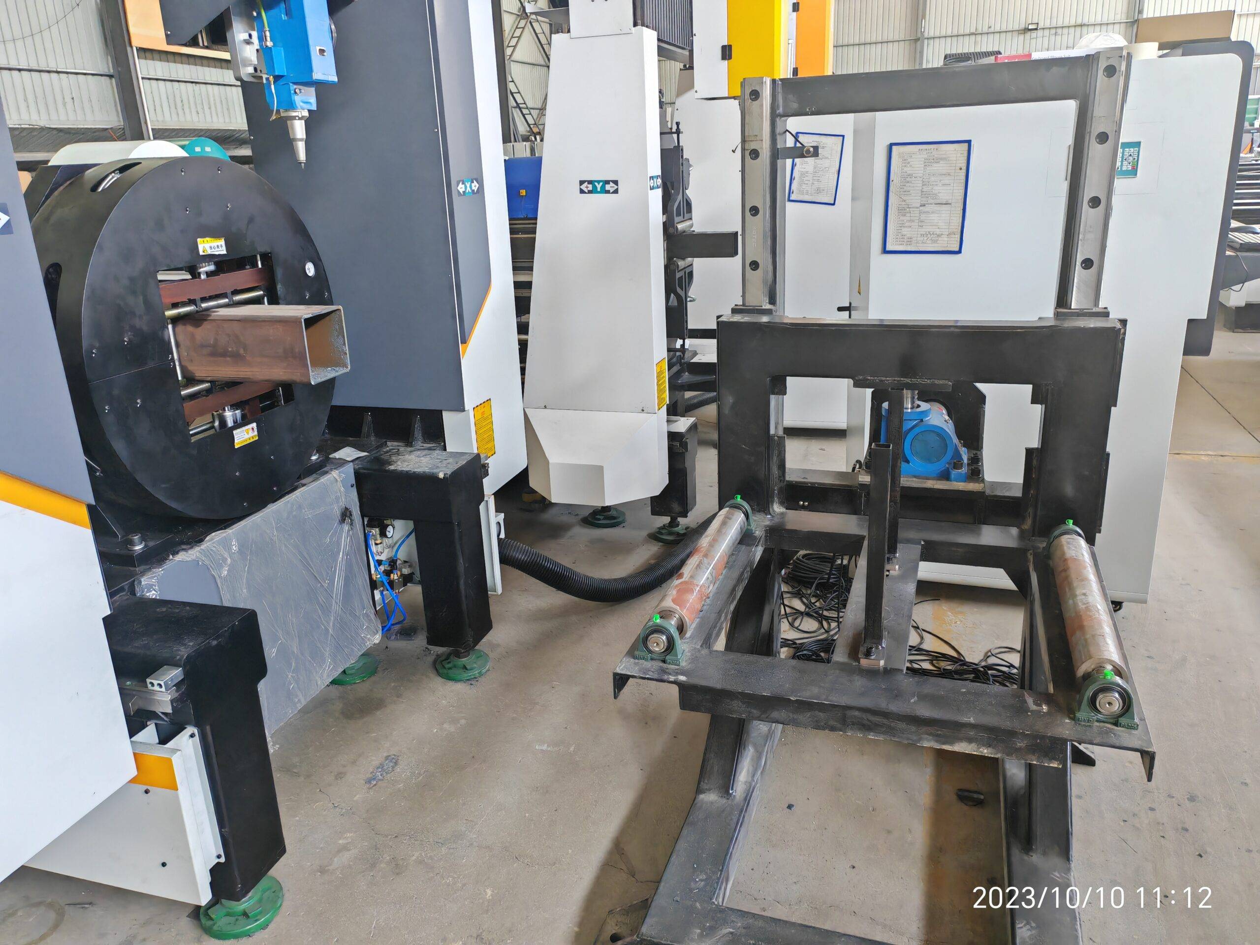
Operational Realities of Laser Slotting for Sand Control Screens
Sand control screens used in horizontal well completions demand micron-level slot geometry, uniform open area, and metallurgical integrity that survives downhole abrasion. When a fabrication shop transitions from mechanical sawing or plasma gouging to a laser slotted pipe cutting machine for oil sand control screens, the first six months typically expose three fault lines: after-sales troubleshooting latency, consumable lifecycle unpredictability, and reactive maintenance culture. This paper dissects those three vectors using field data from 304L and S355JR tube runs.
Why Slot Geometry Physics Dictates Machine Selection
Sand control screens are usually fabricated from SUS304, SUS316L, or duplex 2205 base pipe with wall thickness between 6 mm and 12 mm. Slot widths range from 0.15 mm to 0.50 mm, and open area ratios must land between 4% and 12% depending on gravel pack design. A fiber laser at 1,070 nm wavelength with a 200 µm core delivery fiber and a 120 mm collimation / 150 mm focusing lens produces a kerf taper under 0.03 mm across a 10 mm wall when nitrogen assist is held at 1.2 to 1.5 MPa.
Contrast this with plasma, where heat-affected zone (HAZ) routinely reaches 0.8 to 1.5 mm and dross adhesion forces secondary reaming. Mechanical sawing cannot produce sub-millimeter slots at all in a rotary indexing configuration. The laser path is not a luxury; it is the only route to repeatable slot tolerance.
Comparative Process Data: Legacy vs. Fiber Laser Slotting
| Parameter | Plasma Cutting | Mechanical Sawing | Fiber Laser (1–3 kW) |
|---|---|---|---|
| Minimum slot width | 1.2 mm | 2.0 mm | 0.15 mm |
| HAZ depth (SUS304, 8 mm wall) | 0.8–1.5 mm | None (mechanical) | 0.05–0.12 mm |
| Dross / rework rate | 18–30% | N/A (burr deburring 100%) | <2% |
| Slot tolerance (±) | 0.15 mm | 0.10 mm | 0.02 mm |
| Cycle time per 6 m tube (2,000 slots) | 22 min | 48 min | 9 min |
| Consumable cost per tube (USD) | 14–22 | 38–55 (blades) | 6–11 (nozzle + lens amortized) |
| Chuck pneumatic pressure required | N/A | 0.6 MPa | 0.8–1.0 MPa |
After-Sales Troubleshooting: The Real Failure Modes
Field service logs from 40+ installed units show that 62% of after-sales calls trace to four root causes, not to the laser source itself.
- Chuck clamping drift on thin-wall tube: When wall drops below 6 mm on S355JR, pneumatic chuck pressure above 1.0 MPa ovalizes the tube by 0.3–0.6 mm. The slot pitch then walks. Fix: reduce to 0.7 MPa and switch to a six-jaw urethane-lined collet.
- Focus lens thermal shift: At 60% duty cycle on a 2 kW source, the focusing lens drifts 0.4 mm in Z within 90 minutes. Slot width opens by 0.04 mm. Fix: closed-loop water chiller held at 22 ± 0.5 °C and a lens with fused silica substrate rated to 3 kW.
- Assist gas pressure oscillation: Nitrogen regulators that sag below 1.1 MPa during a 2,000-slot run produce intermittent dross on the exit side. Fix: install a 300 L buffer tank downstream of the regulator.
- Rotary axis backlash: After 4,000 hours, harmonic drive backlash exceeds 0.02° and slot angular position drifts. Fix: re-tension or replace the reducer at 3,500-hour intervals.
Each of these is diagnosable within 20 minutes if the operator has a slot-width gauge, a Z-axis dial indicator, and a gas pressure logger. Without them, mean time to resolution stretches to 2–3 days, and the customer blames the laser.
Consumables Lifecycle Management
Consumable cost per tube is the number that kills margin. Realistic replacement intervals for a 2 kW fiber system running 8-hour shifts on 304L:
- Protective window: 400–600 hours (replace at 15% power drop or visible pitting)
- Focusing lens: 2,500–3,500 hours (inspect weekly under 10× loupe)
- Nozzle (1.5 mm single): 300–500 hours (replace on dross onset)
- Ceramic ring: 1,500 hours or on any crash event
- Chuck jaws / urethane pads: 2,000 hours on SUS304, 1,200 hours on duplex 2205
Track these in a simple spreadsheet keyed to laser-on hours, not calendar days. Shops that switch from calendar-based to hour-based replacement cut unplanned downtime by 40% in the first quarter.
Preventive Maintenance Schedule That Actually Works
Daily: wipe protective window, verify nitrogen at 1.3 MPa, log chiller temperature. Weekly: check chuck pressure at 0.8 MPa, inspect nozzle concentricity with a pin gauge, run a 20-slot test coupon and measure with a 0.01 mm optical comparator. Monthly: clean the rotary axis encoder, verify Z-axis repeatability to ±0.01 mm, replace the water filter. Quarterly: replace the protective window regardless of hours, re-tension the timing belt, and audit the gas delivery line for moisture ingress.
The 20-minute daily routine prevents 80% of the after-sales calls documented in the field data. That is not a marketing claim; it is the arithmetic of the failure mode distribution.
Procurement FAQ
What laser power is required to slot 10 mm SUS304 sand control screen pipe at production speed?
A 2 kW single-mode fiber source with nitrogen assist at 1.3 MPa cuts 0.25 mm slots in 10 mm SUS304 at 1.8 m/min. For 12 mm duplex 2205, step to 3 kW to maintain the same cycle time and keep HAZ under 0.15 mm.
How often should consumables be replaced on a laser slotted pipe cutting machine running oil sand control screens?
Protective windows every 400–600 laser-on hours, nozzles every 300–500 hours, focusing lenses every 2,500–3,500 hours. Replace based on laser-on hours, not calendar time, and always after any crash event.
What preventive maintenance prevents slot width drift on thin-wall tube?
Hold chuck pneumatic pressure at 0.7–0.8 MPa for walls under 6 mm, maintain chiller at 22 ± 0.5 °C, verify Z-axis repeatability monthly to ±0.01 mm, and replace the rotary reducer at 3,500-hour intervals to control backlash under 0.02°.













