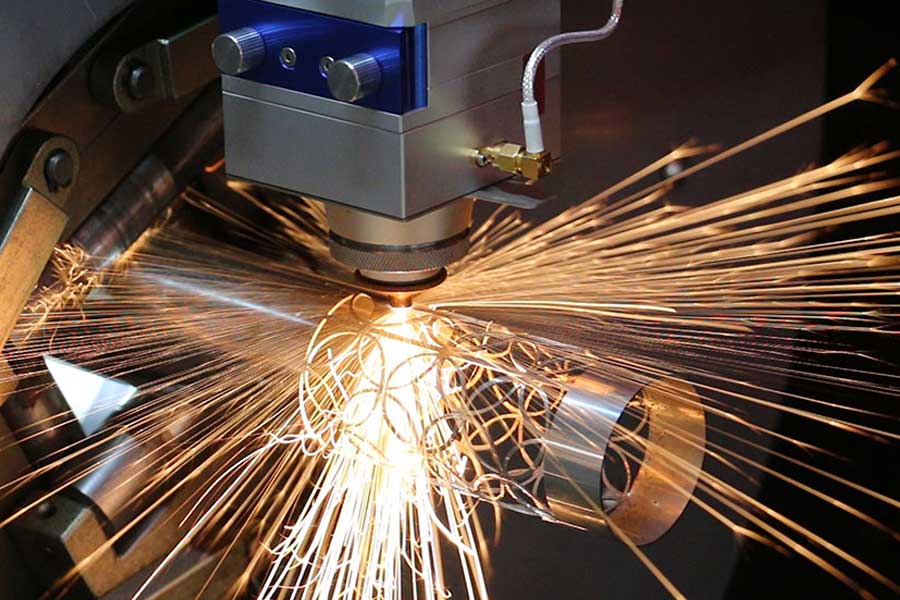
CNC automatic pipe cutter for forklift telescopic mast production: Severe Workshop Condition Adaptation, Thermal Expansion Mitigation, and Stress-Relieved Bed Stability
Forklift telescopic masts are not fabricated from decorative tubing. The inner, intermediate, and outer rail sections on a 3-stage or 4-stage mast are structural load paths that carry vertical compression, bending moment, and torsional whip during lift and tilt cycles. The dominant materials remain S355JR (EN 10025-2) and, in cold-storage or corrosive environments, SUS304 or SUS316L. Wall thickness typically runs 6 mm to 12 mm on outer rails and 4 mm to 8 mm on inner rails, with rail cross-sections that are frequently non-symmetric — C-channels, J-profiles, and rectangular hollow sections with internal weld beads. Cutting these profiles on a CNC automatic pipe cutter for forklift telescopic mast production is a systems-integration problem, not a machine-specification problem. The cutting cell must survive the same environment that the mast itself is built to withstand: abrasive dust, thermal cycling, and vibration transmitted through the shop floor.
Why the Workshop Environment Dictates Machine Architecture
Forklift mast fabrication shops are rarely clean-room operations. Grinding dust from weld preparation, airborne iron oxide from plasma tables, and humidity swings between 30% and 85% RH are normal. A laser cutting cell installed in this environment must be specified around three failure modes that dominate field data:
- Optical contamination: A 6 kW fiber laser with a 100 µm delivery fiber and a 125 mm collimation length will lose 8–12% of effective power within 200 operating hours if the protective window is not purged. Positive-pressure air knives at 0.4–0.6 MPa across the lens module are mandatory, not optional.
- Chuck jaw wear: Pneumatic three-jaw or four-jaw chucks operating at 0.6–0.8 MPa clamping pressure will lose concentricity tolerance (target ≤0.05 mm TIR) after roughly 15,000 clamp cycles if jaw inserts are not hardened to HRC 58–62. Soft jaws deform under the impulse of a 12 mm S355JR tube.
- Bed distortion from thermal load: Continuous cutting of 8 mm SUS304 at 4.5 kW average power dumps 1.2–1.8 kW of waste heat into the machine frame. Without a stress-relieved bed, this manifests as 0.15–0.30 mm drift over an 8-hour shift — enough to scrap a mast rail with a ±0.2 mm cut-length tolerance.
Thermal Expansion Mitigation: The Real Engineering Battle
Thermal growth in a tube cutting cell is not uniform. The chuck assembly, the linear guide rails, and the ball screw all expand at different rates because they see different heat loads. A 6-meter ball screw in a 22 °C shop will grow approximately 0.10 mm per °C rise. If the screw runs 6 °C above ambient after four hours of duty, that is 0.6 mm of positional error at the far end of the stroke — catastrophic for a mast rail that must mate with a roller bracket.
Field-proven mitigation strategies include:
- Symmetrical frame design with stress-relieved weldments: Frames should be annealed after welding (typically 550–600 °C, 2-hour soak, controlled cooling) to eliminate residual stress. This is the single most overlooked specification in low-cost machines.
- Closed-loop temperature compensation: Linear encoders on the X and Y axes, combined with thermocouples bonded to the ball screw and guide rail, allow the CNC to apply real-time compensation. A 0.5 °C resolution thermocouple pair is sufficient for 0.02 mm compensation accuracy.
- Chiller-stabilized laser source: The fiber laser itself should be water-cooled to ±0.5 °C. A 6 kW source running at 60% duty cycle (typical for 8 mm S355JR at 2.8 m/min) rejects roughly 2.4 kW to the chiller loop.
- Cutting gas thermal management: Nitrogen at 1.2–1.5 MPa and oxygen at 0.8–1.2 MPa both expand and cool at the nozzle. Poorly regulated gas delivery causes kerf width variation of 0.05–0.10 mm, which directly affects the fit-up of mast rail end caps.
Comparative Technical Data: Legacy Methods vs. Fiber Laser Cell
The following table reflects field data collected from mast fabrication lines running mixed production of S355JR and SUS304 rails.
| Parameter | Conventional Plasma | Mechanical Saw (Cold) | CNC Fiber Laser Cell |
|---|---|---|---|
| Cut length tolerance (per 3 m) | ±0.8 mm | ±0.5 mm | ±0.10 mm |
| Kerf width | 2.5–4.0 mm | 3.0–5.0 mm (blade) | 0.15–0.30 mm |
| Heat affected zone | 1.5–3.0 mm | None | 0.05–0.15 mm |
| Edge squareness (per 100 mm) | 0.5–1.0 mm | 0.3–0.6 mm | ≤0.05 mm |
| Cycle time, 8 mm S355JR, 1.2 m cut | 45–60 s | 90–150 s | 22–28 s |
| Dross / rework rate | 12–18% | 4–8% (burr) | ≤2% |
| Consumable cost per 1,000 cuts | High (nozzles, electrodes) | Medium (blades) | Low (nozzle + lens) |
| Automation compatibility | Limited | Manual load typical | Full (chuck + auto-loader) |
Stress-Relieved Bed Stability and Chuck Dynamics
The bed of a tube cutting machine is the reference plane for every cut. On a 6-meter or 9-meter machine, the bed must hold flatness within 0.05 mm/m under static load and 0.10 mm/m under dynamic load. Cast iron beds with ribbed cross-sections (minimum 25 mm rib thickness) outperform welded steel beds in damping ratio by a factor of 3–5, but they are heavier and more expensive to ship. The compromise in modern cells is a welded steel bed that has been vibratory stress-relieved and then precision-machined in a single setup.
Chuck synchronization is the second stability pillar. On a mast rail with a non-symmetric cross-section, an unsynchronized front and rear chuck will induce twist during rotation. Field data shows that a 0.5° twist on a 4-meter rail translates to 3.5 mm of end-to-end misalignment — well outside the ±0.5 mm tolerance for roller bracket mounting. Servo-synchronized chucks with absolute encoders and a shared motion bus (EtherCAT or equivalent) are the only reliable solution.
Pneumatic clamping pressure must be tuned per material. For SUS304 with 6 mm wall, 0.5–0.6 MPa is sufficient. For S355JR with 12 mm wall, 0.7–0.8 MPa is required to prevent slip during high-speed rotation. Exceeding 0.9 MPa on thin-wall SUS304 will ovalize the tube by 0.3–0.5 mm — a defect that will not show up until the mast is assembled.
Procurement FAQ
What laser power is required to cut 12 mm S355JR mast rails at production speed?
A 6 kW fiber laser with nitrogen assist at 1.4–1.5 MPa will cut 12 mm S355JR at 1.8–2.2 m/min with a 0.25 mm kerf. A 4 kW source will cut the same material at 0.9–1.1 m/min, which is often insufficient for a two-shift mast line. For mixed SUS304 production, 6 kW is the practical minimum.
How does the machine compensate for thermal drift over an 8-hour shift?
Closed-loop thermal compensation using linear encoders and thermocouples on the ball screw and guide rails is the standard approach. Combined with a stress-relieved bed and a chiller-stabilized laser source, drift can be held under 0.05 mm over an 8-hour shift in a shop with ±5 °C ambient variation.
Can the same cell handle both S355JR and SUS304 without re-tooling?
Yes, provided the cutting parameters are stored in the CNC as material-specific recipes. Nitrogen assist is used for both, but SUS304 requires lower clamping pressure (0.5–0.6 MPa) and slightly higher focal position offset (+0.3 to +0.5 mm) to avoid dross on the bottom edge.













