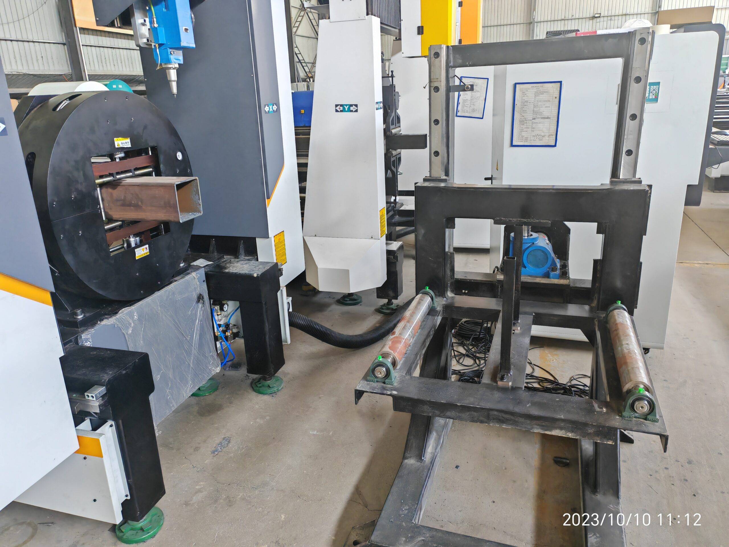
Energy Efficiency and Electro-Optical Optimization in Heavy Duty Tube Laser Cutting for Automotive Chassis Fabrication
When a 12 kW fiber laser is tasked with severing 8 mm wall S355JR structural tubing at 4.2 m/min, the electrical meter at the wall tells a more honest story than any brochure. The real operational cost driver on a chassis line is not the resonator’s nameplate wattage — it is the electro-optical conversion chain, the assist-gas architecture, and how aggressively the duty cycle is managed across a three-shift schedule. Shops evaluating heavy duty tube laser cutting for automotive chassis fabrication need to model wall-plug efficiency, not just cutting speed, because chassis tube geometries — hydroformed rails, cross-members, suspension mounting sleeves — punish inefficient gas delivery and idle laser time harder than flat-plate work ever does.
Electro-Optical Conversion: Where the Kilowatts Actually Go
Modern ytterbium-doped fiber resonators achieve wall-plug efficiency between 30% and 40%. A 10 kW optical output module typically draws 28–33 kW from the facility bus, with the remainder lost to diode pump inefficiency, thermal management, and chiller load. On a tube processing cell running 6,500 hours annually, that 3 kW of parasitic loss translates to roughly 19,500 kWh per year — before the chiller, the dust extraction, and the servo drives are counted. The engineering response is not to buy a smaller laser; it is to match the resonator to the wall thickness distribution of the chassis program. Cutting 2 mm SUS304 hydraulic line brackets with a 12 kW source is electro-optically wasteful; a 4 kW module running at 85% duty cycle on the same geometry consumes 40% less energy per part.
Beam parameter product matters here. A 12 kW source with a 100 µm fiber core delivers a BPP around 0.35 mm·mrad, which is excellent for 6–10 mm carbon steel but produces an oversized kerf on thin-wall Al6061. The energy penalty is real: excess kerf width means excess melt volume, which means excess assist gas and excess laser on-time.
High-Pressure Air and Nitrogen Cost Optimization
Assist gas is the silent budget killer. Cutting 6 mm S355JR with nitrogen at 1.4 MPa through a 2.0 mm nozzle consumes roughly 28–35 Nm³/h. At industrial N₂ pricing of $0.35–$0.60 per Nm³ delivered, a single shift can burn $400 in gas alone. High-pressure compressed air — generated in-house at 1.2–1.5 MPa with a desiccant dryer and filtration to ISO 8573-1 Class 1.2.1 — costs approximately $0.02–$0.04 per Nm³. For chassis tube work in the 3–6 mm range, air cutting with a nitrogen-boosted edge quality protocol reduces gas cost by 85–92% while maintaining acceptable dross characteristics for downstream MIG welding.
The trade-off is edge oxidation. Air-cut S355JR produces a thin oxide layer that must be wire-brushed or acid-pickled before robotic welding. For SUS304, air cutting is generally unacceptable due to chromium depletion at the cut face; nitrogen at 1.5 MPa remains mandatory. The optimization matrix is therefore alloy-specific, not universal.
Chuck Dynamics and Duty Cycle Management
Heavy duty tube processing on 6 m stock with 180 mm OD requires pneumatic chucks clamping at 0.6–0.8 MPa to resist the torsional whip during high-speed rotary positioning. Insufficient clamping pressure at 0.4 MPa produces micro-slippage, which manifests as taper on the cut face and premature nozzle wear. Conversely, over-clamping thin-wall Al6061 above 0.9 MPa deforms the tube oval and destroys concentricity for the next operation.
Duty cycle management on the resonator is equally critical. Running a 12 kW source at 100% duty on 8 mm carbon steel for 45 minutes straight drives the diode junction temperature toward the derating threshold. Modern controllers throttle output to 92–95% to protect the module, which paradoxically increases total cutting time and energy per part. The correct strategy is interleaving thick-wall and thin-wall nests to allow thermal recovery without stopping the machine.
Comparative Process Data: Legacy vs. Fiber Laser
| Parameter | Plasma Cutting | Mechanical Sawing | Fiber Laser (12 kW) |
|---|---|---|---|
| Cut speed on 6 mm S355JR | 1.8 m/min | 0.4 m/min | 4.2 m/min |
| Kerf width | 3.5–4.5 mm | 4.0 mm (blade) | 0.3–0.5 mm |
| Heat affected zone | 1.5–3.0 mm | None | 0.1–0.25 mm |
| Energy per meter cut | 0.85 kWh | 0.42 kWh | 0.18 kWh |
| Assist gas cost per meter | $0.12 (air/Ar mix) | N/A (coolant) | $0.04 (air) / $0.31 (N₂) |
| Post-process requirement | Heavy dross removal | Deburring + facing | Light brush (air cut) |
| Dimensional tolerance | ±0.8 mm | ±0.5 mm | ±0.1 mm |
Green Manufacturing Metrics That Matter
Scope 2 emissions for a tube laser cell are dominated by electricity and delivered gas. A 12 kW fiber cell cutting 6 mm carbon steel with high-pressure air produces approximately 0.42 kg CO₂ per meter of cut when powered by a grid at 0.45 kg CO₂/kWh. The same cut with bottled nitrogen adds 0.28 kg CO₂ equivalent from gas production and transport. Switching to on-site nitrogen generation with a PSA system cuts that figure by 70% and eliminates cylinder logistics — a measurable win for ISO 14064 reporting.
Chiller setpoint optimization is another lever. Raising the cooling loop from 22°C to 26°C reduces chiller compressor load by 12–15% with no measurable impact on resonator stability, provided the diode module’s internal derating curve is respected.
Procurement FAQ
What wall thickness range justifies a 12 kW fiber laser over a 6 kW source for chassis tube work?
If more than 30% of the production mix exceeds 6 mm in S355JR or 5 mm in SUS304, a 12 kW source pays back within 18–24 months through reduced cut time and lower energy per part. Below that threshold, a 6 kW module with a 50 µm fiber delivers better electro-optical efficiency.
Can high-pressure air replace nitrogen for all automotive chassis tube cutting?
No. Air cutting is viable for carbon steels (S355JR, 4130) between 2–8 mm with acceptable edge quality for MIG welding. Stainless grades (SUS304, 316L) and aluminum (Al6061) require nitrogen at 1.2–1.5 MPa to prevent oxidation and maintain corrosion resistance.
What pneumatic clamping pressure is recommended for 180 mm OD structural tubing?
For 4–8 mm wall carbon steel, 0.6–0.8 MPa provides sufficient torsional resistance without ovalization. Thin-wall aluminum or stainless below 3 mm should be clamped at 0.4–0.5 MPa with extended jaw contact pads to distribute load.













