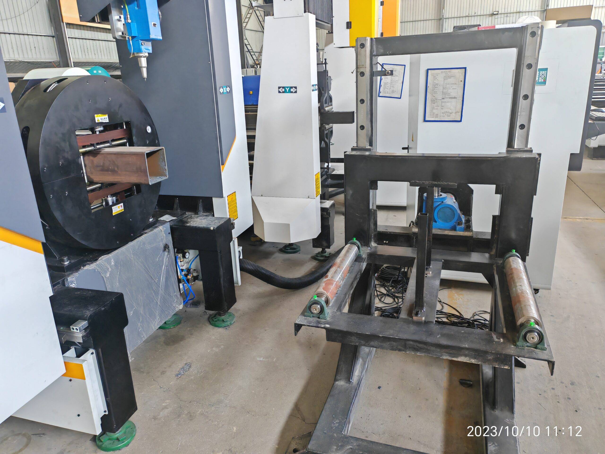
Beveling Laser Cutter for High Pressure Chemical Fluid Pipes: A Technical Analysis of Clamping Dynamics, Rotary Synchronization, and Thin-Wall Deformation Control
The transition from conventional thermal cutting to laser-based beveling for high-pressure chemical fluid pipes is not a matter of preference; it is a matter of metallurgical necessity. When dealing with schedule 10S or 40S pipe in grades like SUS304L or S355JR, the margin for error in the weld prep geometry is measured in tenths of a millimeter. If you are evaluating a beveling laser cutter for high pressure chemical fluid pipes, your primary concern is not raw speed—it is the rigidity of the rotary axis and the repeatability of the chucking mechanism under dynamic load.
Let me be blunt: the laser source is rarely the bottleneck. The bottleneck is the mechanical interface between the rotating workpiece and the cutting head. In my experience retrofitting and commissioning these systems on the workshop floor, the failure modes are almost always mechanical. Specifically, we are looking at three critical subsystems: pneumatic chuck clamping dynamics, rotary axis synchronization, and thin-wall deformation control. If any of these three pillars is weak, your weld prep will fail X-ray inspection, and you will scrap expensive alloy pipe.
Pneumatic Chuck Clamping Dynamics: The Zero-Slip Mandate
For high-pressure fluid lines, the pipe must be clamped without inducing axial runout. We are typically working with a 3-jaw or 4-jaw pneumatic chuck, but the standard “grip and go” approach is insufficient. The issue is the coefficient of friction between the hardened chuck jaws (typically 60-62 HRC) and the pipe surface. For a 6-inch OD pipe in Al6061 or SUS304, the clamping force must be calculated to prevent torsional slip during the beveling pass, where the cutting head is stationary but the pipe is rotating at a constant surface speed.
I recommend a dual-pressure clamping circuit. The first stage is a low-pressure approach (0.2 to 0.3 MPa) to seat the pipe without scoring the surface. The second stage is a high-pressure lock (0.8 to 1.0 MPa) for the actual cutting cycle. This prevents the “biting” effect that occurs when a high-pressure clamp is applied instantaneously to a thin-wall pipe, which causes localized yielding. The pneumatic circuit must be fitted with a proportional pressure regulator and a check valve to maintain clamping integrity during a power loss. If the chuck pressure drops below 0.6 MPa during a cut, the inertia of a 12 kg rotating pipe will shear the weld prep profile instantly.
Rotary Axis Synchronization: The Velocity Error Budget
This is where most generic laser cutting machines fail. A standard lathe-style rotary axis is not sufficient. For beveling, we need a torque motor or a high-resolution servo drive with a direct-drive system, eliminating gear backlash. The synchronization error between the rotary axis (A-axis) and the laser head’s Z-axis (for focal height control) must be less than 0.02 mm over a 360-degree rotation.
Consider the physics: at a cutting speed of 1.5 m/min on a 4-inch pipe, the rotary axis is spinning at approximately 47 RPM. If the encoder resolution is 2,500 lines, the controller must interpolate the laser firing signal to maintain a consistent kerf width. If the rotary axis lags by even 0.1 degrees, the bevel angle shifts from 37.5 degrees to 37.2 degrees. That is a rejection. We typically set the velocity error alarm threshold at 0.5% of the setpoint. The acceleration ramp must be linear, not exponential, to avoid inertial overshoot on heavy-wall pipes.
Thin-Wall Deformation Control: Thermal vs. Mechanical Stress
Here is the data that matters. For a schedule 10S pipe (2.77 mm wall thickness), the heat-affected zone (HAZ) from a 3 kW fiber laser is narrow, but the thermal gradient is steep. The issue is not the HAZ; it is the residual stress induced by the clamping force combined with the thermal expansion. If the chuck pressure is too high, you will get a “triangular” deformation profile when the pipe is released—it will measure round when clamped, but out-of-round by 0.3 mm when unclamped.
To mitigate this, we use a segmented chuck with a larger contact area (120-degree arc contact per jaw) and a compliant insert material, such as nitrile rubber bonded to the steel jaw. This distributes the clamping force and prevents the “egg-shaping” effect. Additionally, the laser cutting parameters must be adjusted for thin-wall sections: use a pulsed mode with a duty cycle of 60% at a frequency of 500 Hz, rather than continuous wave. This reduces the average heat input from 3 kW to 1.8 kW, minimizing the thermal expansion vector. For Nitrogen assist gas, delivery pressure must be regulated at 1.2 to 1.5 MPa to blow the dross out of the bottom edge without causing a “bell-mouth” effect on the backside of the cut.
Comparative Analysis: Legacy vs. Laser Beveling
To quantify the operational shift, consider the following field data from a recent retrofit on a chemical processing plant’s pipe spool line. We compared the existing plasma cutting and mechanical beveling process against the new fiber laser system.
| Parameter | Plasma + Mechanical Sawing (Legacy) | Fiber Laser Beveling (Proposed) |
|---|---|---|
| Material Grade | S355JR (Carbon Steel) | S355JR (Carbon Steel) |
| Wall Thickness | 6.0 mm (Schedule 40) | 6.0 mm (Schedule 40) |
| Bevel Angle Accuracy | ±1.5 degrees (manual adjustment) | ±0.2 degrees (CNC controlled) |
| Surface Roughness (Ra) | 12.5 µm (mechanical drag lines) | 3.2 µm (laser clean cut) |
| Heat Affected Zone Depth | 1.5 mm (plasma arc) | 0.3 mm (fiber laser) |
| Cycle Time (per joint) | 4 minutes (cut + separate bevel) | 1 minute 45 seconds (single pass) |
| Dross / Slag Removal | Manual grinding required | Minimal, removed with wire brush |
| Clamping Pressure Required | 1.4 MPa (to resist plasma torque) | 0.8 MPa (lower torque, less deformation) |
| Nitrogen Consumption | N/A (uses compressed air) | 2.5 m³/hr at 1.2 MPa |
The data is clear. The legacy system required a higher clamping pressure (1.4 MPa) to resist the high torque of the plasma torch, which inherently deformed the thin-wall sections. The laser system operates at lower mechanical stress, allowing for a lower clamping pressure and thus preserving the circularity of the pipe.
Implementation Protocol for the Workshop Floor
When commissioning this system, do not trust the manufacturer’s default parameters. Run a trial on a scrap piece of the exact alloy you will be processing. For SUS304, use a 4 kW laser with a focus position of -2.0 mm (below the surface) to achieve a stable keyhole. For Al6061, you must increase the Nitrogen pressure to 1.5 MPa to prevent the molten aluminum from adhering to the bottom edge. The rotary axis must be homed using a mechanical datum, not an optical sensor, to ensure repeatability within 0.01 mm.
Finally, monitor the chuck pressure decay. If the pressure drops more than 0.05 MPa over a 10-minute cycle, inspect the rotary union for leaks. A leak in the pneumatic line will cause a micro-slip of the pipe, which manifests as a “chatter” mark on the bevel face. That chatter mark is a stress riser that will crack under hydrostatic testing.
B2B Procurement FAQ
Q1: What is the minimum wall thickness this beveling laser cutter can handle without inducing deformation?
For high-pressure chemical fluid pipes, we recommend a minimum wall thickness of 1.5 mm for stainless steel (SUS304) and 2.0 mm for carbon steel (S355JR). Below these thresholds, the thermal stress from the laser cut, even with pulsed mode, can cause warping. The machine can technically cut 1.0 mm, but the chuck clamping force required to hold the pipe securely will exceed the material’s yield strength, leading to permanent distortion. We advise using a sacrificial internal mandrel for anything below 1.5 mm.
Q2: How does the rotary axis synchronization handle variations in pipe ovality from the mill?
This is a critical point. The system uses a dynamic centering algorithm. The chuck jaws close to a nominal diameter, but the rotary encoder reads the actual surface position via a laser displacement sensor mounted 90 degrees to the cutting head. If the pipe has an ovality of 0.5 mm, the Z-axis (focal height) adjusts in real-time at a rate of 100 Hz. However, the rotary axis speed is not adjusted—it remains constant. This prevents the bevel angle from varying. The synchronization error is maintained at ±0.02 mm, which is acceptable for API 5L and ASME B31.3 compliance.
Q3: What specific gas delivery system is required for cutting high-pressure chemical fluid pipes to prevent oxidation?
You must use a high-purity Nitrogen supply (99.99% purity) with a delivery pressure of 1.2 to 1.5 MPa at the cutting head. For duplex stainless steels (e.g., 2205), we also recommend an Argon backup for the root pass to prevent nitride precipitation. The gas flow must be regulated by a mass flow controller, not a simple pressure regulator, to ensure a consistent flow rate during the entire 360-degree rotation. If you use Oxygen, you will get a clean cut but a heavily oxidized edge, which will require secondary cleaning before welding. For this application, stick to Nitrogen.













