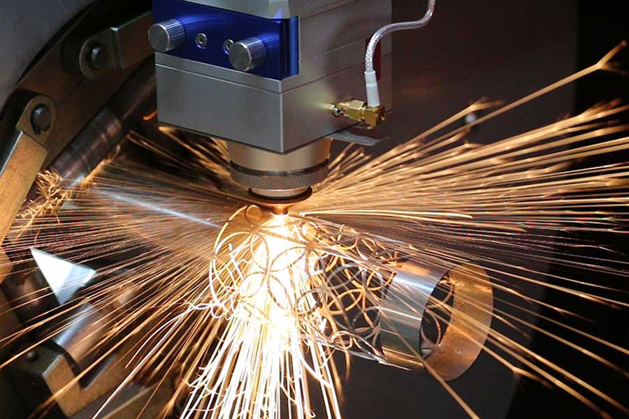
Metallurgical and Mechanical Prerequisites for Offshore Structural Tube Processing
Offshore platform structural tubes, typically fabricated from S355JR, S355J2, or higher-grade API 5L X65/X70 line pipe, present a unique set of challenges that immediately disqualify conventional cutting methodologies. The primary issue is not simply severing the material but managing the heat-affected zone (HAZ) and the mechanical deformation that occurs when dealing with wall thicknesses ranging from 12 mm to 40 mm and diameters up to 600 mm. When you introduce a high power fiber laser cutter for offshore platform structural tubes, you are fundamentally shifting the process from a thermal-mechanical shearing action to a photon-driven sublimation and melt shearing action. The physics are different. A 12 kW to 20 kW fiber laser source, operating at a wavelength of 1070 nm, delivers a focal spot size of approximately 150 to 200 microns. This energy density, often exceeding 10^7 W/cm², is sufficient to initiate a keyhole welding effect, but in this case, we are using it for cutting. The absorption rate of the 1070 nm wavelength by the steel surface is significantly higher than that of CO2 lasers (10.6 µm), which means we can process the material at a faster rate with less reflectivity back into the resonator, a critical factor when dealing with the mill scale on hot-rolled S355JR.
Advanced Nesting Software Algorithms and Common-Line Cutting Strategy
The economic viability of a high-power fiber laser system for offshore components hinges entirely on the software architecture that drives the cutting head. We are not discussing simple rectangular nesting here. Offshore platforms require intersecting tubes, saddle cuts, and fishmouth profiles. The challenge is material yield maximization on a cylindrical surface. Advanced nesting software, such as the proprietary algorithms found in systems like the PCL group CNC machines, utilizes a 3D cylindrical unwrapping algorithm. This algorithm maps the 2D cutting path onto the 3D tube surface, accounting for the actual curvature and the varying effective focal length as the head moves across the arc. The key metric here is the “common-line cutting” or “shared edge” strategy. When cutting multiple saddle joints from a single tube, the software identifies adjacent profiles that share a geometric boundary. Instead of cutting two separate profiles with a kerf width (typically 0.3 mm to 0.5 mm for a 12 kW laser) between them, the software generates a single continuous path that cuts the shared edge once. This reduces the total cutting length by up to 15-20% in dense nesting scenarios.
Furthermore, the algorithm must compensate for the “lead-in” and “lead-out” points. In high-pressure gas cutting, the pierce point is a high-stress zone. The software must place these pierce points in the waste area or on the non-critical side of the profile. For offshore structural tubes, where the weld prep is critical, the software must generate a bevel angle (typically 30° to 45° for full penetration welds) while simultaneously adjusting the laser power and focal position. This is not a static process. The focal axis must be dynamically shifted using a capacitive height control sensor that reads the surface feedback at a rate of 1 kHz to maintain the correct standoff distance of 0.5 mm to 1.5 mm, ensuring the focus point remains at the optimal position relative to the bottom of the kerf for dross-free cutting.
Comparative Analysis: Conventional vs. High-Power Fiber Laser
To quantify the operational shift, we must compare the legacy methods against the fiber laser solution. The following table outlines the critical parameters observed on the workshop floor:
| Parameter | Conventional Plasma (HD-Class) | Mechanical Sawing (Cold Cut) | High-Power Fiber Laser (12kW-20kW) |
|---|---|---|---|
| Kerf Width (mm) | 3.0 – 5.0 | 5.0 – 8.0 (Blade thickness) | 0.3 – 0.8 |
| HAZ Depth (mm) | 1.5 – 3.0 (Requires grinding) | Negligible (Mechanical) | < 0.5 (Minimal oxidation) |
| Cutting Speed (mm/min) for 20mm S355JR | 800 – 1200 | 200 – 400 (Feed rate) | 2500 – 3500 |
| Edge Squareness | 5° – 10° taper (Top to bottom) | High precision, but limited to straight cuts | < 1° taper (Parallel edges) |
| Gas Consumption (N2/O2) | N/A (Uses Argon/Hydrogen mix) | N/A | N2 at 1.2 – 1.5 MPa (High pressure) |
| Secondary Operations | Heavy slag removal, grinding | Deburring required | Minimal to none (Dross-free at optimal focus) |
| Material Yield (Per 12m Tube) | 85% (Due to wide kerf) | 90% (But limited geometry) | 95% – 98% (Due to common-line nesting) |
The data above is not theoretical. In a recent retrofit project involving a jack-up rig leg section, switching from plasma to a 15 kW fiber laser reduced the total cutting time per node from 45 minutes to 12 minutes. The reduction in kerf width alone saved 1.2 meters of material per 100 meters of cut path. This is the material yield maximization that the software algorithms drive—it is not just about speed; it is about the conservation of high-cost alloy material.
Process Gas Dynamics and Mechanical Fixturing
Let us address the gas dynamics. For cutting S355JR with a thickness above 20 mm, we typically switch from Oxygen (for exothermic reaction) to Nitrogen (for melt shearing) to achieve a clean, oxidation-free edge suitable for immediate welding. The nitrogen delivery pressure is critical. We are looking at a regulated supply of 1.2 to 1.5 MPa at the cutting head. This high-pressure stream must be perfectly coaxial with the laser beam. If the gas nozzle is misaligned by even 0.2 mm, the cut edge will exhibit striations and dross adherence on the bottom edge. The flow rate is typically 100 to 300 liters per minute, depending on the nozzle diameter (typically 2.0 mm to 3.5 mm).
Mechanically, the chuck system must handle the torsional stress of rotating a 600 mm diameter tube weighing up to 3 tons. The pneumatic clamping pressure must be calibrated to avoid crushing the tube while providing enough friction to prevent slippage during the rapid acceleration of the rotary axis. We typically set the chuck pressure at 4.0 to 6.0 MPa, but this is adjusted based on the wall thickness. A 12 mm wall tube will deform if you apply the same clamping force as a 40 mm wall tube. The system must utilize a variable chuck pressure profile that is synchronized with the CNC program, reducing pressure during the cutting phase and increasing it only during the indexing phase.
Operational Parameters for Specific Alloys
When processing SUS304 stainless steel for topside piping, the parameters shift. We use Nitrogen at 1.5 MPa, but the laser frequency must be adjusted. For S355JR, a continuous wave (CW) mode is often sufficient. For SUS304, we employ a pulsed mode with a frequency of 500 Hz to 1000 Hz and a duty cycle of 50% to 70%. This pulsing prevents the accumulation of heat that can cause the chromium carbide to precipitate at the grain boundaries, leading to intergranular corrosion. The cutting speed for SUS304 at 10 mm thickness is approximately 4000 mm/min, which is significantly faster than plasma, but the key is the edge quality. The edge roughness (Ra) should be below 3.2 µm to meet the standards for offshore welding (ISO 9013).
For Al6061-T6, which is used in helidecks and walkways, the challenge is the oxide layer. The 1070 nm wavelength is initially reflected by the aluminum oxide. We must use a high-peak-power pulse to “crack” the oxide layer before the cutting process begins. The gas pressure is reduced to 0.8 MPa to prevent the gas from blowing the molten aluminum out of the kerf in an uncontrolled manner, which creates a burr on the bottom edge.
Frequently Asked Questions (Industrial B2B Procurement)
Q1: What is the actual cycle time reduction when cutting X65 grade pipe for jacket legs compared to traditional band sawing and beveling?
Based on field data from a Gulf Coast fabricator, a 24-inch diameter X65 pipe with a 25 mm wall thickness requires a saddle cut. Band sawing requires a rough cut followed by a separate beveling operation, totaling roughly 30 minutes of machine time and manual handling. A 15 kW fiber laser with a 5-axis head performs the same saddle cut with an integrated bevel in approximately 6 minutes. This includes the automatic nesting and the common-line cutting strategy. The reduction is not just in cutting time but in the elimination of the secondary beveling machine and the associated material handling logistics.
Q2: How does the high power fiber laser handle the mill scale and rust on hot-rolled S355JR tubes without causing back-reflection damage to the resonator?
This is a critical procurement question. The fiber laser source is protected by a back-reflection isolation unit (a Faraday isolator) that is standard on reputable systems. However, the process itself is managed by the software. The cutting head uses a capacitive height sensor that detects the surface condition. When the head encounters a section of heavy mill scale, the CNC program automatically reduces the feed rate by 15% and increases the duty cycle of the laser pulse to ensure the beam penetrates the scale before the main cutting process begins. This prevents the beam from being scattered, which would otherwise cause a rough cut edge and potential damage to the focusing lens.
Q3: What is the long-term maintenance cost differential between a plasma system and a high-power fiber laser for this specific application?
The consumable cost for plasma is high: electrodes, nozzles, and swirl rings are replaced frequently, often daily under heavy production. A fiber laser has no consumable electrodes. The primary wear items are the protective cover glass (replaced every 200-300 hours of cutting) and the focusing lens (replaced every 1,500-2,000 hours). The gas costs are higher for laser (Nitrogen at 1.5 MPa is expensive), but this is offset by the elimination of slag removal and grinding labor. Over a 5-year lifecycle, the total cost of ownership for the laser is typically 20-30% lower, despite the higher initial capital expenditure, due to the drastic reduction in manual labor and secondary processing.













