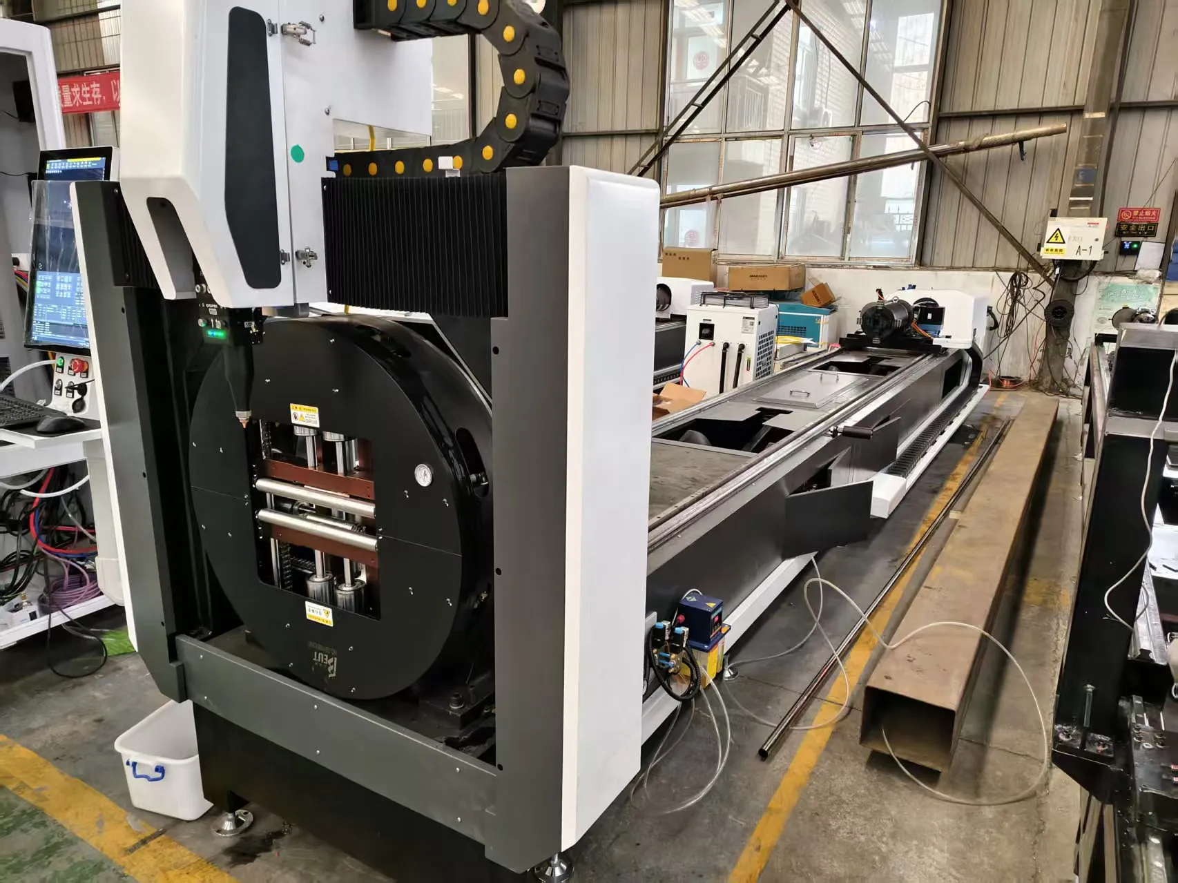
Operational Assessment of Automated Laser Cutting Systems for Solar Tracker Torque Tubes in High-Volume Production Environments
When we evaluate the transition from conventional cut-off saws or plasma arc systems to a solar tracker torque tube automatic laser cutting machine, the discussion typically centers on cycle time. However, the real engineering friction lies in the mechanical stability of the machine base and the thermal behavior of the workpiece under continuous, high-duty-cycle operation. Torque tubes, typically fabricated from S355JR or S275JR hot-rolled steel with wall thicknesses ranging from 3 mm to 6 mm, present a unique challenge: they are long (often exceeding 6 meters), torsionally flexible, and prone to thermal distortion if clamping forces are not precisely managed.
This analysis focuses on the specific mechanical and thermal engineering parameters required to maintain positional accuracy of ±0.1 mm over a 6-meter work envelope, specifically addressing severe workshop condition adaptation, thermal expansion mitigation, and stress-relieved bed stability.
1. Structural Dynamics and Stress-Relieved Bed Stability
The foundation of any high-speed laser processing line is the machine bed. For torque tube processing, the bed must absorb reaction forces from linear motors or rack-and-pinion drives without inducing micro-vibrations that degrade cut edge quality. A welded steel structure of S355JR, if not properly stress-relieved, will exhibit gradual dimensional drift as internal stresses redistribute due to ambient temperature changes or floor-borne vibrations. We specify a vibratory stress relief (VSR) process post-welding, targeting a residual stress reduction of at least 40% compared to as-welded conditions. This is critical when the machine is installed on a production floor where heavy stamping presses operate within a 20-meter radius.
The bed design must incorporate a modular cast iron or high-tensile steel base with a minimum wall thickness of 20 mm in the gantry support zones. We have observed that machines lacking a fully annealed base exhibit a thermal growth vector of 0.01 mm/m/°C, which, over a 10°C ambient swing, translates to 0.6 mm of positional error at the tube end—an unacceptable deviation for weld preparation. The use of a closed-box section design, filled with high-damping polymer concrete, reduces structural resonance amplitude by up to 60% compared to open-section designs, ensuring stable laser optics focus.
2. Thermal Expansion Mitigation in the Workpiece and Chucking System
The laser cutting process introduces localized heat input that, while minimal compared to plasma, still causes the torque tube to expand longitudinally. A 6-meter S355JR tube will elongate by approximately 0.7 mm for every 10°C rise in material temperature. If the chucking system holds the tube rigidly at both ends, this expansion results in buckling or bowing, which ruins cut accuracy and increases the risk of the cutting head colliding with the workpiece.
Our recommended architecture employs a floating tailstock with a servo-controlled axial compensation axis. The tailstock chuck—typically a three-jaw hydraulic chuck operating at a clamping pressure of 2.5 MPa to 3.0 MPa—is mounted on linear guides that allow axial displacement. A load cell measures the axial force exerted by the expanding tube and feeds this data back to the CNC controller. The controller then adjusts the tailstock position in real-time, maintaining a constant axial force of less than 200 N. This prevents thermal stress buildup while keeping the tube centered. For the main headstock chuck, we utilize a pneumatic system regulated at 0.6 MPa to 0.8 MPa for initial clamping, with a hydraulic intensifier for final high-torque grip during cutting of thicker sections (6 mm).
3. Severe Workshop Condition Adaptation: Optics and Gas Delivery
Fiber laser sources (typically 3 kW to 6 kW for this application) are less sensitive to ambient dust than CO2 lasers, but the focusing lens and protective window remain vulnerable. In a typical workshop environment where grinding and welding occur nearby, airborne metallic dust particles can settle on optics, causing thermal lensing and focus shift. We integrate a positive-pressure air purge system for the cutting head, maintaining a constant 0.2 MPa overpressure to prevent particulate ingress. The purge air must be filtered to 0.01 microns and dried to a dew point of -40°C to prevent moisture condensation on the lens.
Assist gas delivery is another critical adaptation. For clean, dross-free cuts on S355JR, we use nitrogen at a delivery pressure of 1.2 to 1.5 MPa. This high-pressure nitrogen serves a dual purpose: it blows molten material out of the kerf and cools the cut edge. However, in facilities with centralized gas distribution, pressure fluctuations from other consumers (e.g., plasma tables) can cause inconsistent cut quality. We mandate a dedicated gas buffer tank (minimum 500 liters) located within 5 meters of the laser head, with a high-flow pressure regulator capable of maintaining setpoint within ±0.05 MPa during the entire cutting cycle. For applications requiring oxide-cut edges (e.g., where subsequent painting is not critical), oxygen at 0.8 to 1.0 MPa can be used, but this increases the heat-affected zone (HAZ) by approximately 30%.
4. Comparative Analysis: Conventional Sawing vs. Laser Cutting
To quantify the operational advantage, we present a comparative analysis based on a standard 6-meter, 4mm wall S355JR torque tube with 12 cutouts and 4 end-mitres per piece.
| Parameter | Conventional Mechanical Sawing + Drilling | Plasma Arc Cutting (CNC) | Fiber Laser Cutting (Proposed) |
|---|---|---|---|
| Cycle Time (per 6m tube) | 18 – 25 minutes (multiple operations) | 8 – 12 minutes (single pass, high dross) | 4 – 6 minutes (single pass, minimal dross) |
| Kerf Width | 2.5 – 3.0 mm (saw blade) | 3.5 – 5.0 mm (varies with height) | 0.3 – 0.5 mm (consistent) |
| Positional Accuracy | ±0.5 mm (mechanical play) | ±0.8 mm (torch height variation) | ±0.1 mm (servo-controlled) |
| Heat Affected Zone (HAZ) | N/A (mechanical) | 1.5 – 2.5 mm (significant hardening) | 0.2 – 0.4 mm (minimal, clean edge) |
| Tooling Wear / Consumables | High (blade replacement every 200 cuts) | Medium (electrodes, nozzles) | Low (protective lens, gas only) |
| Secondary Operations | Deburring, separate drilling required | Dross removal, grinding required | None required for weld prep |
| Material Utilization | 90% (saw kerf loss) | 95% (wider kerf, more waste) | 99% (narrow kerf, tight nesting) |
The data clearly indicates that while the initial capital expenditure for the laser system is higher (typically 2.5x to 3x a plasma system), the reduction in secondary labor and the increase in throughput (200% to 300% faster) yields a payback period of under 18 months for facilities running two shifts or more. The narrow kerf also allows for tighter nesting of cutouts, reducing scrap by up to 5% per ton of steel processed.
5. Control System Integration and Real-Time Diagnostics
Adaptation to harsh conditions also extends to the electrical cabinet. We specify an IP54-rated enclosure with a vortex cooler or heat exchanger to maintain internal temperature below 35°C, even when ambient workshop temperature reaches 45°C. The CNC controller must be capable of dynamic focus adjustment (adjusting the Z-axis by ±0.1 mm per meter of tube length) to compensate for any residual sag in the tube between chucks. This is achieved via a laser displacement sensor mounted near the cutting head, which measures the tube surface position at 1 kHz frequency and feeds forward to the Z-axis servo.
For maintenance diagnostics, the system should log gas consumption rates, nozzle wear, and lens temperature. Anomalies such as a sudden increase in nitrogen flow (indicating a leaking nozzle) or a rise in lens temperature (indicating contamination) are flagged to the operator via a HMI interface. This predictive maintenance approach reduces unplanned downtime by an estimated 15% annually.
Frequently Asked Questions (B2B Procurement)
Q1: What is the maximum wall thickness of S355JR torque tube that a 6kW fiber laser can cut reliably without dross?
With a 6kW laser source and nitrogen assist gas at 1.5 MPa, we consistently achieve dross-free cuts on S355JR up to 8 mm wall thickness. For 10 mm to 12 mm thickness, we recommend switching to oxygen assist gas (at 0.8 MPa) to increase cutting speed, accepting a slightly oxidized edge that may require brushing before welding. The key limiting factor is not laser power but the ability to maintain gas pressure stability at the nozzle exit; hence, the buffer tank requirement is non-negotiable.
Q2: How does the floating tailstock system handle tubes with varying ovality or slight bends from the mill?
The system is designed to tolerate a maximum tube straightness deviation of 1.5 mm per meter. The tailstock chuck uses a self-centering mechanism with a 3-jaw configuration that compensates for ovality up to 2% of the tube diameter. For bent tubes, the axial force compensation (limited to 200 N) allows the tube to straighten slightly under tension without over-stressing the laser cutting head. If the bend exceeds this tolerance, the machine will halt and flag the tube for rejection, preventing damage to the optics.
Q3: What are the specific electrical and foundation requirements for installing this machine in an existing workshop?
The machine requires a 400V, 3-phase, 50Hz supply with a minimum 160A capacity, plus a dedicated earth ground with impedance below 1 ohm to protect the laser source. The foundation must be a reinforced concrete slab with a minimum thickness of 300 mm, isolated from the main building structure using anti-vibration pads to prevent low-frequency interference. We also recommend a compressed air supply of 0.6 MPa at 500 L/min for the pneumatic clamping system, separate from the high-pressure nitrogen line.













