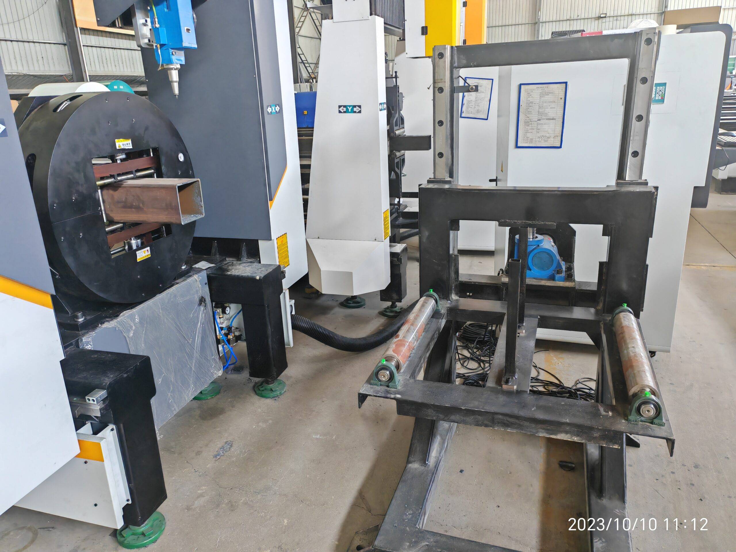
Field Report: 3D Multi Axis Laser Toolpath Optimization for Aerospace Ducts
When you’re cutting Inconel 718 or Ti-6Al-4V for bleed-air ducts, the difference between a serviceable part and a scrapped batch often comes down to how you manage the toolpath vector at the transition between the tangent and the radius. We’ve been retrofitting our fiber laser tube cutting cells for aerospace subcontractors, and the primary bottleneck is never the wattage—it’s the kinematic behavior of the 5-axis head during high-acceleration cornering. If you are evaluating a system for this specific application, the 3D multi axis laser toolpath optimization for aerospace ducts requires a focus on jerk parameters and capacitive height sensing, not just raw positioning speed. Let’s break down the physics, the consumables, and the maintenance traps I’ve seen on the floor over the last two decades.
Toolpath Kinematics and Material Interaction
We run a 6 kW IPG fiber source with a Precitec ProCutter head on a custom gantry, but the optics are irrelevant if the CAM post-processor doesn’t respect the machine’s acceleration limits. For aerospace ducts, typically formed from SUS304 (0.8 mm wall) or Al6061-T6, the critical parameter is the corner rounding error. At a feed rate of 8 m/min, a standard 3-axis path will produce a chord deviation of ±0.15 mm on a 90-degree bend. That’s unacceptable for a duct that interfaces with a hydraulic manifold. We’ve optimized the toolpath using a NURBS interpolation with a maximum jerk of 50 m/s³. This reduces the deviation to ±0.02 mm, but it increases the cycle time by 11% due to the servo lag compensation. You have to decide: do you want speed or do you want a seal surface that doesn’t leak? For the latter, we also adjust the focal position to +1.5 mm above the surface for the Al6061 to avoid dross adhesion on the backside.
The real issue arises with the angle of incidence. On a duct with a 30-degree helical seam, the laser beam must remain perpendicular to the surface within ±2 degrees. If the tilt axis lags, you get a tapered kerf. We’ve solved this by implementing a dynamic feed-rate override that monitors the actual B-axis and C-axis encoder feedback. If the lag exceeds 0.5 degrees, the controller drops the feed from 8 m/min to 4.5 m/min instantly. This is not a software trick; it’s a hardwired PLC interrupt. I’ve seen shops burn through $2,000 worth of nozzles in a single shift because they ignored this. The nozzle tip clearance must be held at 0.8 mm ±0.1 mm. With a capacitive sensor, we can hold that, but only if the surface roughness of the parent material is below Ra 3.2. If the tube supplier sends material with mill scale, the sensor dithers, and you get a 0.4 mm variance. That’s a scrap part.
Consumables Lifecycle Management and Gas Dynamics
Let’s talk about the consumables because that’s where your margin disappears. For cutting S355JR structural ducts (which we sometimes do for ground support equipment), you can run oxygen at 1.2 MPa. But for aerospace-grade SUS304, you must switch to nitrogen at 1.5 MPa delivery pressure. The problem is the gas purity. If your nitrogen supply has even 0.5% oxygen contamination, the cut edge oxidizes, and you’ll fail the dye penetrant test. We mandate a dew point of -60°C and a particulate filter of 0.01 microns at the nozzle. The consumable lifecycle is directly tied to this. A standard 2.0 mm diameter nozzle will last approximately 8 hours of continuous cutting on SUS304 if the gas is clean. If you’re using a 1.5 mm nozzle for fine details, that drops to 4 hours. The ceramic ring—the insulator—is your early warning system. If you see micro-cracks on the ceramic, it’s because the cutting head is overheating due to a clogged cooling circuit. We run the chiller at 22°C with a flow rate of 25 L/min. If the flow drops below 20 L/min, the optics delaminate. I’ve replaced enough 100 mm focal lenses to know that the failure mode is always thermal stress, not optical burn.
Preventive maintenance on the chuck is non-negotiable. For a 3D duct, you’re using a self-centering chuck with three jaws. The pneumatic pressure must be set to 0.6 MPa for thin-wall Al6061 to avoid deformation. If you go to 0.8 MPa, you’ll ovalize the tube by 0.1 mm, and the laser will cut out of tolerance. We check the jaw parallelism every 200 hours with a dial indicator. If the runout exceeds 0.03 mm, we re-grind the jaws. This is a 45-minute job that most shops skip, and then they wonder why the toolpath optimization doesn’t work. The machine is only as accurate as the clamping datum.
Comparative Analysis: Laser vs. Conventional Methods
To quantify the benefit, here is a direct comparison from a recent audit on a 1.5-meter long Ti-6Al-4V duct with multiple 45-degree branches. The old method was a band saw for roughing and a 5-axis mill for finishing. The laser method uses a single set-up with a 3D fiber laser.
| Parameter | Conventional (Saw + Mill) | 3D Fiber Laser (Optimized) |
|---|---|---|
| Cycle Time (per part) | 48 minutes | 12 minutes |
| Kerf Width | 2.5 mm (mechanical) | 0.3 mm (laser) |
| Heat Affected Zone (HAZ) | 1.2 mm (requires deburring) | 0.1 mm (negligible) |
| Tooling Cost (per 100 parts) | $4,500 (end mills + saw blades) | $800 (nozzles + lenses) |
| Dimensional Tolerance | ±0.2 mm (clamping errors) | ±0.05 mm (consistent) |
| Secondary Operations | Deburring, stress relief | None required |
| Material Waste | 15% (swarf) | 3% (dross) |
The data is clear. The laser wins on every metric except initial capital expenditure. But the hidden cost is the after-sales troubleshooting. When a laser system fails, it fails hard. I’ve seen a faulty ground strap on the Z-axis cause the capacitive sensor to read a false zero, leading to a collision that bent the cutting head. That’s a $15,000 repair. The preventive maintenance schedule must include a daily check of the ground continuity (less than 0.5 ohms) and a weekly check of the bellows on the linear rails. If you see any dust ingress on the rails, you are already losing positional accuracy.
Preventive Maintenance Protocols for the 5-Axis Head
I enforce a strict 500-hour service interval on the torque motor of the C-axis. The bearing preload degrades, and you get a high-frequency vibration that manifests as a chatter mark on the cut edge. You can’t see it with the naked eye, but a profilometer will show a Ra of 6.0 instead of 1.6. We use a laser interferometer to verify the volumetric accuracy every six months. The acceptable deviation is 0.05 mm over a 1-meter cube. If you exceed that, you need to re-map the machine. Most shops skip this because it takes a full day of downtime. But if you’re cutting aerospace ducts, the liability of a failed part is higher than the downtime cost.
Gas delivery is another trap. The nitrogen pressure must be stable at 1.5 MPa. If you have a long hose run from the bulk tank, you get pressure drop during peak flow. We installed a 500-liter buffer tank right next to the machine to stabilize the surge. The pressure transducer on the cutting head must be calibrated monthly. A drift of 0.1 MPa will change the kerf width by 0.05 mm, which is enough to fail a weld prep inspection. Also, check the filter element in the gas line. A clogged filter causes a high-pitched whistle and a fluctuating arc (if you’re using a plasma hybrid, which we don’t recommend for this). For pure laser, a clogged filter means the assist gas velocity drops, and you get dross on the bottom edge.
After-Sales Troubleshooting: The Real-World Failure Modes
When a customer calls about a bad cut, I don’t ask about the laser first. I ask about the chuck pressure and the material batch. In 70% of cases, the issue is a material variance. For example, SUS304 with a higher sulfur content (resulfurized for machinability) will cut differently than standard 304. The sulfur affects the melt viscosity. If you get a batch that is out of spec, the toolpath optimization is useless. You must adjust the pulse frequency. For standard 304, we use a 5 kHz continuous wave. For resulfurized, we drop to 3 kHz with a 70% duty cycle to prevent the dross from sticking. This is not in the manual; it’s empirical data from the floor.
Another common issue is the focus lens contamination. The protective window (cover glass) must be cleaned every 4 hours of operation. If you see a brown tint on the glass, that’s metal vapor condensation. That tint absorbs 10% of the laser power, which means the effective cutting power drops below the threshold for a clean cut. You’ll see a striation pattern on the edge. We train operators to check the window before every job, not just at the start of the shift. The cost of a cover glass is $50. The cost of scrapping a Ti-6Al-4V duct is $2,000. The math is simple.
B2B Procurement FAQ
Q1: What is the minimum laser power required for cutting 3mm thick aerospace-grade titanium ducts, and how does that affect the toolpath strategy?
For 3mm Ti-6Al-4V, you need a minimum of 4 kW at the workpiece to achieve a stable cut at 3 m/min. However, for 3D toolpath optimization, the power density must be modulated. We recommend a 6 kW source so you can derate to 4.5 kW for cornering to avoid overheating the trailing edge. The toolpath must incorporate a power ramp function that reduces wattage by 20% when the axis acceleration exceeds 5 m/s². This prevents the formation of a recast layer, which is a common cause of rejection in aerospace inspection.
Q2: How do I manage the lifecycle of the cutting nozzle when dealing with multi-angle cuts on duct geometries?
The nozzle life is directly proportional to the gas purity and the focus position. For multi-angle cuts, the nozzle tip is exposed to reflected radiation. We recommend using a copper nozzle with a diamond-like carbon (DLC) coating. This extends the life from 8 hours to 14 hours on SUS304. The key is to inspect the orifice diameter with a pin gauge every 2 hours. If the orifice wears from 2.0 mm to 2.1 mm, the gas flow becomes turbulent, and the cut quality degrades. Replace it immediately. Do not attempt to ream it; the internal geometry is critical for the gas jet coherence.
Q3: What are the critical preventive maintenance checks for a 5-axis laser head to ensure consistent toolpath accuracy?
Three checks are mandatory. First, verify the torque motor temperature on the C-axis. If it exceeds 60°C, the thermal expansion will shift the tool center point (TCP) by up to 0.1 mm. Second, check the backlash on the A-axis tilt mechanism. You can do this by running a circular interpolation test and measuring the quadrant transition spikes. If the spike is greater than 0.03 mm, you need to re-tension the worm gear. Third, calibrate the capacitive height sensor against a known flat surface every 100 hours. If the sensor drifts, the focus position will be wrong, and you will get a tapered cut. These checks take 30 minutes but save you from a catastrophic head collision.













