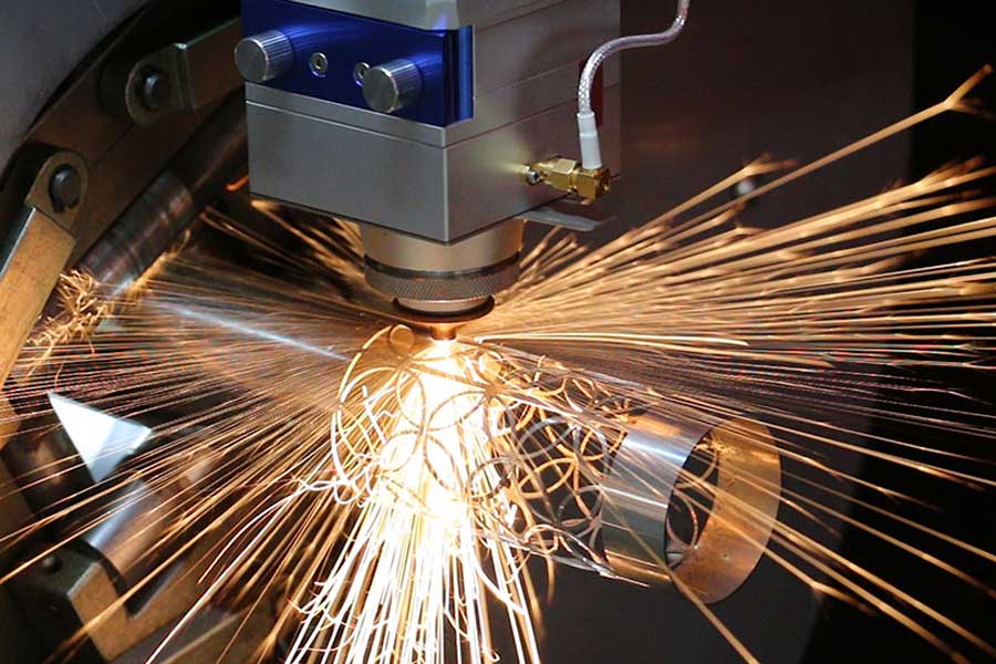
Process Engineering Assessment: High-Throughput Tube Laser Systems for Ergonomic Chair Frame Production
When we evaluate the shift from conventional fabrication to an automatic fiber laser tube cutter for ergonomic office chair frames, we are not discussing a simple tool replacement. We are discussing a fundamental change in the physics of the cutting zone, the thermal load on the parent material, and the statistical distribution of dimensional variance across a batch of 10,000 units. The primary driver here is not just speed, but the deterministic control of the kerf width and the heat-affected zone (HAZ), which directly dictates the structural integrity of the weld joint downstream. Let’s break down the mechanical specifics that matter on the floor, specifically focusing on processing efficiency, dynamic speed benchmarks, and the critical tolerances for structural beveling and root gaps.
The ergonomic chair frame is a brutal test case for automation. We are dealing with thin-wall tubes, typically S355JR carbon steel (1.5 mm to 2.0 mm wall thickness) or SUS304 stainless for higher-end mesh frames, and increasingly Al6061-T6 for lightweight executive models. The geometry is not simple linear cuts; we have saddle cuts, fish mouths, and oblique end cuts that must mate perfectly to form the lumbar support and armrest substructures. A mechanical saw or plasma unit struggles with the positional accuracy required for these complex intersections, often leaving a root gap variance of ±0.5 mm. That variance is a weld defect waiting to happen. The fiber laser system, operating with a 3 kW to 6 kW resonator, changes the game by maintaining a positional tolerance of ±0.05 mm, but the real magic lies in the dynamic response of the axes.
Dynamic Speed Benchmarks and Axis Acceleration Profiles
Let’s talk numbers, not marketing fluff. On a standard 6-meter loading system with a 3kW laser source, we are looking at cutting speeds for S355JR 2mm wall thickness at approximately 8 to 10 meters per minute using Nitrogen as the assist gas. However, the bottleneck in chair frame production is rarely the straight cut; it is the piercing time and the acceleration/deceleration curves on the contour. A high-end automatic tube cutter will have a maximum positioning speed of 120 m/min, but the critical metric is the acceleration rate—typically 1.5 G to 2 G on the linear axes and a rotary chuck speed of up to 300 RPM. This allows the machine to maintain a constant cutting velocity even when navigating the tight radii of a chair armrest bracket, preventing the “dwell marks” that plague slower systems.
We must also discuss the duty cycle. In a two-shift operation, the laser source is running at a 95% duty cycle. The cutting head is equipped with a capacitive height sensor that adjusts focal position at 1 kHz frequency to compensate for tube ovality. If the tube supplier delivers material with an ovality exceeding 0.3 mm, the sensor will struggle, and you will see a degradation in cut edge quality—specifically, a drag line on the lower edge. For chair frames, this is unacceptable because the lower edge is often the visible seam. The solution is a self-centering chuck system with pneumatic clamping pressure set between 0.6 MPa and 0.8 MPa. This pressure must be calibrated precisely; too low, and the tube slips during high-torque rotation; too high, and you induce deformation in the thin-wall Al6061 material, which will spring back after cutting and ruin the frame geometry.
Structural Beveling and Root Gap Tolerances
Now, we get to the core of structural integrity. The ergonomic chair frame is subjected to cyclic fatigue loading, specifically the BIFMA X5.1 standard for seating. The failure point is almost always the weld joint between the seat post and the side rails. To achieve a full-penetration weld without a backing ring, you need a precise Y-bevel or V-bevel cut on the tube end. The automatic fiber laser cutter must be capable of angular cutting (beveling) up to 45 degrees without reducing the cutting speed by more than 30%. This is achieved through a 3D cutting head with a tilt axis that rotates the nozzle relative to the workpiece.
The critical parameter here is the root face height. For a 2mm wall tube, you want a root face of 0.5 mm ± 0.1 mm. If the laser cuts this too thin, the weld pool will blow through. If it is too thick, the weld penetration is insufficient. The laser system maintains this tolerance through a rigid gantry structure and a high-resolution torque motor on the tilt axis. Furthermore, the assist gas management is critical. For stainless steel (SUS304), we use pure Nitrogen at a delivery pressure of 1.5 MPa to prevent oxidation and ensure a clean, silver-colored cut edge. For carbon steel (S355JR), we switch to Oxygen at 1.2 MPa to accelerate the cutting process, accepting a slight oxide layer that must be cleaned prior to powder coating. The transition between these gas regimes must be automatic and instantaneous, controlled by the CNC program, to avoid operator error.
Comparative Analysis: Legacy vs. Laser Automation
To illustrate the operational delta, consider the following table comparing the legacy mechanical sawing/plasma approach versus the modern automatic fiber laser tube cutter for this specific application. The data reflects a batch size of 500 frames (approx. 4,000 cut parts).
| Parameter | Conventional Sawing + Plasma | Automatic Fiber Laser Tube Cutter |
|---|---|---|
| Cutting Speed (S355JR, 2mm) | 0.5 m/min (saw) / 1.5 m/min (plasma) | 8.5 m/min (O2 assist) |
| Positional Accuracy | ±0.3 mm (mechanical tolerance) | ±0.05 mm (servo-driven) |
| Beveling Capability | Requires secondary milling operation | In-process 3D beveling (0-45°) |
| Root Gap Consistency | ±0.5 mm (high scrap rate) | ±0.1 mm (consistent weld prep) |
| Heat Affected Zone | 1.5 mm – 2.0 mm (plasma) | < 0.1 mm (fiber laser) |
| Material Handling | Manual loading, individual part handling | Automated tube loading, unloading, sorting |
| Cycle Time per Frame Set | 18 minutes (including deburring) | 4.5 minutes (net cutting) |
| Operator Intervention | High (measurement, deburring, alignment) | Low (supervisory only) |
The data above is not theoretical. The reduction in cycle time from 18 minutes to 4.5 minutes is a direct result of eliminating the deburring step (the laser cut edge is ready for welding) and the secondary milling for bevels. The scrap rate reduction, from roughly 8% down to 0.5%, is achieved through the elimination of mechanical vibration and thermal distortion.
In terms of floor integration, the laser system requires a dedicated chiller unit to maintain the resonator temperature at a stable 22°C ± 1°C. The cutting area must be enclosed with Class 1 laser safety housing, and the dust extraction system must handle the fine metallic particulate generated during cutting, specifically for the aluminum alloys which produce a highly reactive dust that poses a combustion risk if not properly managed. The pneumatic system for the chucks and the clamping fixtures must be supplied with dry, filtered air at a dew point of -40°C to prevent moisture from affecting the optics.
Finally, the economic justification is tied to the “cost per cut.” While the initial capital expenditure is significantly higher than a saw, the consumable cost is lower. The laser cutting head’s protective window (a 25mm diameter quartz disc) costs approximately $15 and lasts for roughly 200 hours of cutting time. The nozzle, depending on the material, lasts for 100 hours. Compare this to the cost of saw blades (which need resharpening every 500 cuts) and plasma electrodes (which degrade rapidly). The ROI is typically realized within 18 months for a facility producing over 50,000 frames annually.
Industrial B2B Procurement FAQ
Q1: What is the maximum wall thickness we can process on an automatic tube laser cutter for chair frames without compromising the edge quality for welding?
For ergonomic chair frames, you are typically in the 1.0 mm to 3.0 mm wall thickness range. A 3kW laser source will handle up to 4mm carbon steel efficiently, but for 3mm and above, you will see a slight increase in the kerf width and a reduction in cutting speed to maintain a dross-free edge. For Al6061, the limit is around 3mm before you need to switch to a higher-power source (6kW) to maintain the same speed and avoid the formation of a hard oxide layer on the cut edge, which complicates the welding process.
Q2: How does the system handle the varying tube lengths and diameters required for different chair models without extensive changeover time?
The modern systems utilize a fully automatic loading magazine that can hold up to 5 tons of tube stock. The CNC program automatically adjusts the chuck clamping pressure based on the tube diameter and wall thickness, which is read from a barcode or RFID tag on the bundle. Changeover time between different profiles is typically under 60 seconds, as the system does not require manual tool changes; only the program parameters and the chuck jaws (if the diameter range exceeds the jaw’s mechanical limits) need adjustment.
Q3: What specific maintenance protocols are required for the laser cutting head to ensure consistent bevel accuracy over time?
The critical maintenance is the calibration of the tilt axis. We recommend a daily check of the nozzle centering using a calibration ring. The protective window must be inspected every 8 hours of operation for spatter. More importantly, the ceramic nozzle holder must be torqued to the manufacturer’s specification (typically 8 Nm) to prevent gas leakage, which will cause a fluctuation in the assist gas pressure and result in inconsistent cut edge quality. The linear guides on the Z-axis should be greased every 500 hours with a lithium-based grease, and the bellows should be checked for tears to prevent dust ingress into the bearing blocks.













