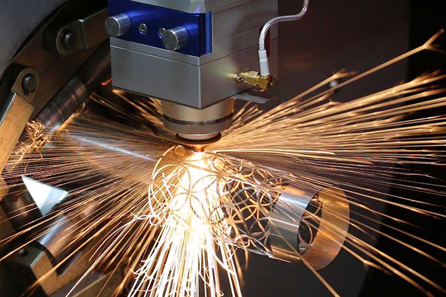
Operational Assessment: Continuous Feeding Fiber Laser Integration for Standard Structural Box Tubing
When we evaluate the shift from batch-based processing to a continuous feeding fiber laser for standard structural box tubing, we are not discussing a simple upgrade in cutting speed. We are fundamentally altering the mechanical load path, the thermal input profile, and the consumable wear curves that define your maintenance schedule. In my two decades of commissioning these systems across fabricating shops handling S355JR and S235JR profiles, the most critical failure point is not the laser source itself—it is the synchronization between the servo-driven feed rollers and the cutting head’s focal point. On a standard 6-meter line, if your feed system’s positional accuracy drifts beyond ±0.15 mm over a 12-meter run, you will see a measurable increase in dross adhesion on the bottom edge of the cut, specifically on the trailing end of the tube. This is the first diagnostic sign that your pinch roller pressure is degrading, not a laser optics issue.
After-Sales Troubleshooting: The Physics of Misalignment and Thermal Drift
Let’s get into the raw mechanics of a typical failure mode. On a continuous feed line handling 80x80x4 mm box section, we run a 3 kW fiber source at a cutting frequency of 5 kHz with a 95% duty cycle. The assist gas—typically nitrogen at 1.4 MPa for a clean, oxide-free edge—is delivered through a 2.0 mm nozzle. When the operator reports a sudden spike in cutting time or a rough surface finish (Ra > 3.2 µm), the first thing I check is not the cutting program. I check the chuck pneumatic pressure. If your clamping system is set to 0.6 MPa but the tube has a slight bow (tolerance of 1 mm/m per EN 10219), the feed rollers will induce a micro-vibration at the cutting head. This vibration, measured at 0.05 mm amplitude, causes the laser beam to strike the material at an angle, effectively increasing the kerf width by 0.1 mm and forcing the nitrogen jet to lose its laminar flow. The result is a recast layer that is 0.2 mm thick on the inside of the tube, which is a nightmare for downstream welding preparation.
In my troubleshooting protocol, I always instruct the site engineer to run a “dry cycle” test. Disengage the laser, run the tube through the feed system at 8 m/min, and measure the runout using a dial indicator at the chuck. If the runout exceeds 0.3 mm, the problem is mechanical. If it is within tolerance, then we move to the optical path. We check the protective window (the cheapest consumable) for any micro-splatter. On SUS304 stainless steel, if you are using oxygen at 1.2 MPa for high-speed cutting (over 3 m/min), you will get a buildup of chromium oxide on the lens. This is a consumable lifecycle issue that is often misdiagnosed as a laser power drop. The lens should be inspected every 8 hours of runtime, not every 40 hours as many operators assume. The cost of a protective window is negligible compared to the cost of a damaged ceramic nozzle or, worse, a scratched focusing lens.
Consumables Lifecycle Management: Data-Driven Replacement Schedules
Let’s talk about the economics of the wear parts. In a conventional plasma system cutting structural tubing, you are looking at a consumable life of roughly 2 hours of arc-on time for a set of electrodes and nozzles. With a mechanical saw, you are looking at blade sharpening every 500 cuts. With the continuous feeding fiber laser, the consumable profile shifts dramatically. The primary wear items are the focus lens (usually a 127 mm focal length lens for 3-4 kW systems), the protective window, and the cutting nozzle. In a high-volume shop running Al6061-T6 tubing, the nozzle life is approximately 120 hours of cutting time, provided the assist gas pressure is kept stable. If the nitrogen supply pressure fluctuates below 1.0 MPa due to a clogged filter in the gas delivery line, the nozzle will overheat and deform. I have seen nozzle orifices go from 2.0 mm to 2.5 mm in a single shift under these conditions, which immediately ruins the cut quality on the next part.
To manage this, I recommend a strict lifecycle matrix based on cutting hours, not calendar time. For the protective window, replace it every 40 hours of runtime or immediately upon any visual inspection showing micro-pitting. For the focus lens, inspect every 200 hours, but replace it at 500 hours if you are cutting galvanized or painted material, as the zinc vapor will coat the lens. The feed rollers are the most overlooked consumable. On a continuous feed system, the polyurethane coating on the drive rollers wears down. If you are feeding 6-meter tubes, the roller makes contact with the entire length. After 10,000 linear meters of feed, the roller diameter reduces by 0.5 mm. This changes the linear speed calibration, causing the laser to overseam or underscan. You must recalibrate the feed encoder every 2,000 meters of processed tube, or you will see a positional error of up to 2 mm on the final cut length.
Preventive Maintenance: The Critical Path for Uptime
Preventive maintenance on this equipment is not about changing filters. It is about managing thermal expansion and mechanical backlash. The gantry or the track system that holds the cutting head is subject to heat from the cutting process. If the cooling system for the laser resonator is set to 22°C but the ambient shop floor temperature is 35°C, you will get condensation on the optics. This is a silent killer. I mandate a daily check of the dew point in the optical housing. The relative humidity must be below 60% inside the cutting head enclosure. We install a desiccant breather on the optical housing and check it every Monday morning.
For the mechanical side, the rack and pinion drive on the gantry needs to be greased with a lithium-based EP2 grease every 100 hours. But the critical check is the backlash. If you measure more than 0.05 mm of backlash on the pinion, you will get a “ghost line” on the cut edge—a slight step that is invisible to the naked eye but will cause stress risers in the final welded structure. I recommend a laser interferometer test on the linear axes every 6 months. This is non-negotiable for structural applications where the tube will be used in load-bearing frames.
Comparative Analysis: Conventional vs. Continuous Fiber Laser
| Parameter | Conventional Plasma / Sawing | Continuous Feeding Fiber Laser |
|---|---|---|
| Kerf Width (80x80x4 mm S355JR) | 3.5 mm (plasma) / 4.0 mm (saw) | 0.3 mm |
| Heat Affected Zone (HAZ) | 1.5 mm – 2.0 mm | < 0.1 mm |
| Cutting Speed (6m/min feed rate) | 0.8 m/min (plasma) | 3.5 m/min (with 3kW laser) |
| Consumable Cost per 1000 cuts | $45 (electrodes/nozzles) | $12 (protective windows/nozzles) |
| Edge Squareness Tolerance | ±1.5° (plasma) / ±0.5° (saw) | ±0.2° |
| Assist Gas Consumption (per hour) | N/A (plasma uses air) | N₂ at 1.4 MPa, 25 m³/hr |
| Setup Time for New Profile | 15 minutes (manual tooling change) | 2 minutes (automatic parameter recall) |
| Dross Formation | Heavy, requires grinding | Minimal, often none on clean steel |
This table highlights the operational shift. The laser’s advantage is not just speed; it is the elimination of secondary operations. When you remove the grinding step, you remove the dust, the labor cost, and the potential for operator error. However, this efficiency is entirely dependent on the maintenance discipline discussed above. A laser that is not maintained will degrade to the performance level of a plasma cutter within 6 months, but with higher electricity costs.
FAQ: Procurement and Operational Considerations
Q1: What is the realistic payback period for a continuous feeding fiber laser when switching from plasma cutting on structural box tubing?
Based on a 2-shift operation (16 hours/day) processing 10 tons of S355JR box section per week, the payback period is typically 18-24 months. This calculation includes the reduction in consumable costs (approximately 70% savings), the elimination of the deburring/grinding station labor (saving roughly 2 man-hours per ton), and the reduction in material waste due to the narrow kerf (saving 3% of material cost). However, this assumes you are running at a 75% machine utilization rate. If your utilization drops below 50%, the payback extends beyond 3 years, making a high-power plasma system with a plate marker a more fiscally sound choice.
Q2: How does the nitrogen assist gas quality affect the cutting edge on stainless steel (SUS304) box tubing?
For SUS304, the nitrogen purity must be 99.995% or higher. If you are using a lower grade (99.9%), the oxygen content in the gas will cause a discoloration on the cut edge and a slight oxidation layer that is visible as a gold or blue tint. This is not just a cosmetic issue; it reduces the corrosion resistance of the cut edge, which is critical for architectural applications. You must also verify the delivery pressure stability. If the pressure drops below 1.2 MPa during a cut, the nitrogen jet becomes turbulent, which creates a striation pattern on the cut face with a depth of 0.1 mm. This is unacceptable for parts that will be visible in the final assembly. I always recommend installing a local nitrogen buffer tank (minimum 500 liters) near the machine to stabilize the pressure spikes from the main supply line.
Q3: What is the most common mechanical failure on the feed system, and how do we prevent it?
The most common failure is the premature wear of the lower drive rollers. These rollers are usually made of hardened steel with a knurled surface to grip the tube. If the tube has mill scale (which is common on hot-rolled S235JR), the scale acts as an abrasive. It will wear down the knurling within 3,000 linear meters of feed. Once the knurling is smooth, the roller slips, causing the tube to stop momentarily. This “stick-slip” motion creates a burn mark on the tube surface at the cutting head. Prevention is simple: install a wire brush station before the feed rollers to remove loose mill scale. Alternatively, specify a hardened roller with a tungsten carbide coating. This increases the roller cost by 40% but extends the life by 400%.













