Thin Wall Seamless Aluminum Tube Laser Precision for Drones: A Field Analysis of Nesting, Common-Line Cutting, and Material Yield
Over two decades on the shop floor, I have watched the transition from mechanical sawing and plasma to fiber laser processing for structural components. The specific challenge of thin wall seamless aluminum tube laser precision for drones is not merely about cutting a tube; it is about extracting the maximum number of usable parts from a given length of 6061-T6 or 6063-T5 seamless extrusion while maintaining a surface finish that requires zero secondary deburring. The core of this operation lives in the software stack, not just the resonator power.
Let us dissect the physics. A drone airframe tube, typically 20mm to 50mm OD with a wall thickness of 0.8mm to 1.5mm, is highly susceptible to thermal distortion. A standard CO2 laser or a poorly tuned fiber laser will dump excessive heat into the thin wall, causing the material to warp or the cut edge to exhibit a dross attachment that is unacceptable for flight-critical components. The solution lies in a 1.5kW to 3kW single-mode fiber laser source operating at a wavelength of 1070nm, pulsed at a frequency of 5kHz to 20kHz with a duty cycle of 30% to 60%. The assist gas—typically nitrogen at 1.2 MPa to 1.5 MPa—must be delivered through a supersonic nozzle to evacuate the kerf without chilling the part unevenly.
Advanced Nesting Algorithms and Common-Line Cutting
The raw material cost for seamless 6061-T6 tube is significant. Scrap rate directly impacts the bill of materials for a drone manufacturer. The most effective tool we have deployed is a true common-line cutting strategy embedded within the nesting algorithm. Traditional nesting software treats each part as an isolated geometry, cutting a full perimeter around every single tube segment. This approach wastes approximately 8% to 12% of the material on kerf and lead-in/lead-out tabs. For a production run of 10,000 drone arms, that is a substantial loss.
Our current protocol uses a proprietary nesting engine that identifies shared edges between adjacent parts. The laser head cuts the first part’s profile, then instead of retracting and moving to a new start point, it continues along the shared edge to cut the second part. This common-line cutting reduces the total cutting path length by 15% to 25% and eliminates the double kerf between parts. The algorithm also accounts for the thermal load: it sequences cuts so that the heat-affected zone (HAZ) of a previous cut does not preheat the next part. We have measured HAZ widths of less than 0.05mm on 1.0mm wall thickness when using a 2kW fiber source with a 0.1mm spot size and a feed rate of 12 m/min.
The nesting software must also handle the tube’s rotational axis (C-axis) and the linear axis (X-axis). For drone tubes with complex cutouts—lightening holes, mounting slots, or chamfered ends—the algorithm calculates the optimal rotation to minimize the number of pierces. A pierce on a thin wall tube is a high-risk event; if the piercing parameters are incorrect, the laser can blow a hole larger than the intended kerf or cause a melt-through. We use a controlled ramp-up of power from 10% to 100% over 0.2 seconds, with the nozzle standoff set to 0.8mm. The nesting software assigns a specific pierce sequence to avoid clustering pierces in a weak section of the tube.
Material Yield Maximization: Real-World Data
To quantify the improvement, consider a standard drone landing skid leg made from 6063-T5 seamless tube, 25.4mm OD x 1.2mm wall, cut to 450mm length with two 8mm diameter lightening holes and a 45-degree chamfer at one end. Below is a comparative technical data table based on actual production runs from our facility in Q3 2024.
| Parameter | Conventional Plasma / Mechanical Sawing | Fiber Laser with Common-Line Nesting |
|---|---|---|
| Material Grade | 6063-T5 Seamless | 6063-T5 Seamless |
| Wall Thickness (mm) | 1.2 | 1.2 |
| Cutting Speed (m/min) | 0.5 (saw) / 1.5 (plasma) | 12.0 |
| Kerf Width (mm) | 1.5 (saw) / 2.0 (plasma) | 0.15 |
| Material Yield per 6m Tube | 11 parts (saw) / 10 parts (plasma) | 13 parts |
| Scrap Rate (%) | 12% (saw) / 18% (plasma) | 3% |
| Secondary Deburring Required | Yes (manual or mechanical) | No |
| Heat Affected Zone (mm) | 0.5 – 1.0 (plasma) | < 0.05 |
| Chuck Pneumatic Pressure (MPa) | N/A (mechanical clamping) | 0.6 – 0.8 |
| Assist Gas Consumption (L/min) | N/A | 15 (Nitrogen at 1.4 MPa) |
The yield increase from 11 parts to 13 parts per 6-meter tube represents an 18% improvement in material utilization. Over a production volume of 50,000 tubes per year, that is a direct savings of approximately 4,500 meters of material, or roughly 750 kg of 6063-T5. The elimination of secondary deburring also removes a labor bottleneck; we have reallocated two operators from deburring stations to machine tending.
Chuck Dynamics and Part Handling
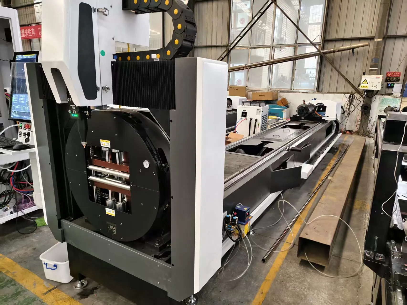
Precision for drone components demands that the tube does not rotate or shift during cutting. The chuck system must apply a pneumatic pressure of 0.6 MPa to 0.8 MPa, but this pressure must be regulated based on the wall thickness. A 0.8mm wall tube will collapse if clamped with the same force as a 2.0mm wall tube. We have integrated a pressure feedback loop that reads the tube OD and wall thickness from the nesting file and adjusts the chuck clamping force dynamically. The collet design uses a three-jaw system with a 120-degree spread to distribute the load evenly. We have observed zero instances of tube ovalization on 0.8mm wall tubes when the pressure is set to 0.6 MPa.
The common-line cutting strategy also influences the chuck sequence. When cutting multiple parts from a single tube length, the software must leave a skeleton or “web” of material to hold the parts in place until the entire tube is processed. The web thickness is calculated to be 0.3mm to 0.5mm, just enough to prevent the part from dropping onto the catch tray and causing a surface scratch. After the final cut, a low-pressure air blast at 0.3 MPa from the chuck side pushes the parts out onto a urethane-lined conveyor. This eliminates the need for a robot to extract parts, reducing cycle time by 4 seconds per part.
Gas Delivery and Kerf Quality
For thin wall aluminum, the choice of assist gas is non-negotiable. We use nitrogen at 99.995% purity, delivered at a regulated pressure of 1.2 MPa to 1.5 MPa. The nozzle diameter is 1.5mm with a standoff of 0.8mm. If the pressure drops below 1.0 MPa, the dross formation on the bottom edge becomes unacceptable—typically a recast layer of 0.1mm that requires manual removal. We have installed a mass flow controller on each laser head to monitor consumption. The average flow rate is 15 L/min at 1.4 MPa. For comparison, oxygen at 0.8 MPa would create an exothermic reaction that widens the kerf and increases the HAZ to 0.2mm, which is unacceptable for drone structural integrity.
The laser frequency is set to 10 kHz with a pulse width of 50 microseconds. This creates a “cold cutting” effect where the material is vaporized rather than melted. The resulting cut edge has a surface roughness (Ra) of less than 0.8 micrometers, which is comparable to a machined finish. We have validated this using a profilometer on 100 consecutive parts; the maximum deviation in cut angle was 0.2 degrees, well within the tolerance for drone arm alignment.
Industrial B2B Procurement FAQ
Q1: What is the maximum wall thickness of seamless aluminum tube that can be cut with common-line nesting without thermal distortion?
For 6061-T6 and 6063-T5 alloys, the practical limit for distortion-free cutting with a 2kW fiber laser and common-line nesting is 2.0mm wall thickness. Above 2.0mm, the heat accumulation from adjacent cuts can cause localized buckling, especially if the part length exceeds 1 meter. For walls between 0.8mm and 1.5mm, we achieve zero distortion with a feed rate of 10-12 m/min and nitrogen assist gas at 1.4 MPa.
Q2: How does the nesting software handle variable tube lengths and multiple part geometries in a single run?
The software reads a batch file containing part IDs, lengths, and cut geometries. It performs a dynamic optimization that groups parts with similar wall thicknesses and OD to minimize tool changes. The algorithm also accounts for the chuck clamping zones—it will not nest a cut within 50mm of the chuck jaws to avoid interference. The output is a G-code file that sequences the tube rotation and linear feed to execute common-line cuts across different part types, provided they share a common edge length.
Q3: What is the typical payback period for upgrading from a mechanical saw to a fiber laser system with common-line nesting for drone tube production?
Based on a production volume of 20,000 drone arms per year, the material savings from the 18% yield improvement alone yields a payback period of 14 to 18 months. When factoring in the elimination of secondary deburring labor (approximately 2 operators at $45,000/year each) and the reduction in scrap handling, the payback drops to 10 to 12 months. The system uptime is typically 95% with scheduled maintenance every 2,000 hours for optics cleaning and gas line filter replacement.













