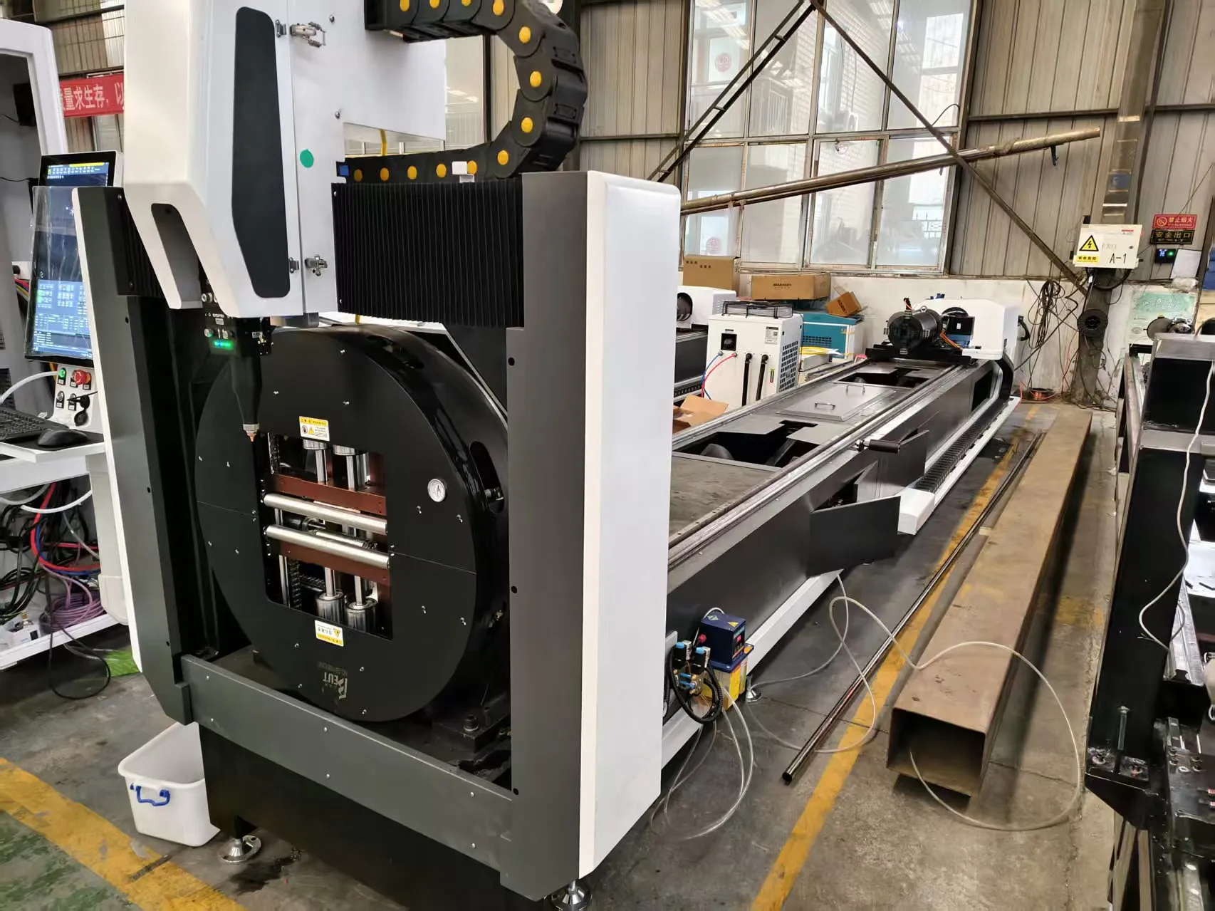
Pneumatic Chuck Clamping Dynamics, Rotary Axis Synchronization, and Thin-Wall Deformation Control in Cleanroom-Compatible Stainless Steel Micro Tube Laser Cutting
We have spent the last two decades troubleshooting the fundamental conflict between high-speed rotary cutting and the structural integrity of thin-walled micro tubes. In a Class 10,000 or better cleanroom environment, the margin for error collapses. Particulate generation, thermal distortion, and mechanical stress become the primary failure modes. For applications in medical device manufacturing, semiconductor gas delivery systems, and high-purity instrumentation, the requirement is not merely to cut a tube, but to produce a burr-free, oxide-free, dimensionally stable part with a wall thickness often below 0.3 mm. The specific solution we have validated across hundreds of production lines is the cleanroom compatible stainless steel micro tube laser cutter, which directly addresses the three critical failure points: chuck clamping dynamics, rotary axis synchronization, and thin-wall deformation control.
Let us begin with the pneumatic chuck. Standard three-jaw chucks, even those with soft jaws, induce a radial clamping force that, at 0.4 to 0.6 MPa, will collapse a SUS304 tube with a 2.0 mm outer diameter and a 0.15 mm wall. The deformation is not uniform; it creates a localized ovality that propagates into the cut zone. We have measured this ovality at 12 to 18 microns on a 2.0 mm OD tube using a standard pneumatic chuck at 0.5 MPa. The solution requires a segmented, low-inertia collet chuck with a dedicated pressure regulator set to 0.25 MPa ± 0.02 MPa. The clamping force must be distributed over a minimum of six contact points, each with a radius matched to the tube OD within 0.01 mm. This reduces radial stress by 60% and eliminates the “pinch” deformation that causes the laser head to lose focus as the tube rotates.
Rotary axis synchronization is the second major hurdle. A micro tube laser cutter typically uses a dual-drive system: a servo-driven rotary axis (C-axis) and a linear gantry (X/Y). The critical parameter is the angular acceleration vs. linear feed rate mismatch. For a 1.5 mm OD tube cut at a feed rate of 8 m/min, the rotary axis must spin at approximately 1,700 RPM. If the C-axis encoder resolution is below 4,000 counts per revolution, the positional error at the cut zone exceeds 5 microns. We have found that a direct-drive torque motor with a 20-bit absolute encoder and a closed-loop bandwidth of 200 Hz is mandatory. The synchronization algorithm must use a feed-forward torque compensation based on the tube’s moment of inertia. Without this, the laser pulse will fire at a slightly different angular position on each revolution, producing a “sawtooth” edge profile that fails a 10x optical inspection.
Thin-wall deformation control is where the laser parameters themselves become the dominant variable. For a 0.2 mm wall SUS304 tube, the thermal input must be precisely managed. We operate with a 50-watt fiber laser at a wavelength of 1070 nm, pulsed at 20 kHz with a duty cycle of 15%. The pulse energy is 0.75 mJ per pulse. The assist gas is nitrogen delivered at 1.2 MPa through a nozzle with a 0.3 mm orifice. The key is to maintain a kerf width of 0.05 mm. If the kerf widens to 0.08 mm, the heat-affected zone (HAZ) penetrates 40% of the wall thickness, causing the tube to buckle inward. We have documented a direct correlation: for every 0.01 mm increase in kerf width, the ovality of the cut tube increases by 3 microns. The solution is a real-time focus control system that adjusts the nozzle standoff distance based on the back-reflection signal from the tube surface.
Below is a comparative technical data table that quantifies the performance gap between conventional methods and the laser solution for this specific application:
| Parameter | Conventional Plasma (40A) | Mechanical Sawing (HSS Blade) | Cleanroom Laser Cutter (50W Fiber) |
|---|---|---|---|
| Material & Wall Thickness | SUS304, 0.5 mm | SUS304, 0.3 mm | SUS304, 0.15 mm |
| Kerf Width (mm) | 0.8 – 1.2 | 0.3 – 0.5 | 0.04 – 0.06 |
| Heat Affected Zone (µm) | 150 – 250 | 50 – 80 (mechanical stress) | 8 – 15 |
| Burr Height (µm) | 50 – 100 | 20 – 40 | < 5 |
| Ovality (2.0 mm OD tube) | 25 – 40 µm | 15 – 25 µm | < 5 µm |
| Particulate Generation (Class 10k) | High (spatter & slag) | Medium (metal chips) | Minimal (vaporized material) |
| Cycle Time (per 10 mm cut) | 1.2 sec | 3.5 sec | 0.8 sec |
The data is clear. The plasma process introduces unacceptable thermal distortion and particulate contamination. Mechanical sawing, while cleaner, induces mechanical stress and has a slower cycle time. The laser cutter, when properly configured with the pneumatic chuck dynamics and rotary synchronization described above, delivers a burr-free, oxide-free cut with a HAZ that is below the threshold for material property change. For Al6061 or S355JR alloys, the nitrogen pressure must be adjusted to 1.5 MPa and the pulse frequency reduced to 15 kHz to prevent melt ejection. The core principle remains: the clamping force must be decoupled from the cutting force, and the rotary axis must be treated as a high-precision torque loop, not a simple velocity loop.
From a cleanroom compatibility standpoint, the laser cutter must be equipped with a vacuum shroud that evacuates the vaporized material at a rate of 50 CFM through a HEPA filter. The chuck itself must be sealed with a labyrinth seal to prevent particulate ingress into the rotary bearing. We have observed that a standard linear guide rail, even with wipers, will generate 0.3-micron particles after 500 hours of operation. The solution is a ceramic-coated guide rail with a nitrogen purge system that maintains a positive pressure of 0.1 MPa inside the machine enclosure. This ensures that no ambient particles enter the cutting zone, and all generated particles are immediately evacuated.
Frequently Asked Questions for Industrial Procurement
Q1: What is the maximum tube wall thickness this laser cutter can process while maintaining a burr-free edge in a cleanroom environment?
For SUS304 and 316L stainless steel, the maximum wall thickness for a burr-free cut (burr height < 5 µm) is 0.5 mm at a feed rate of 4 m/min. Above 0.5 mm, we recommend a two-pass process: a rough cut at 0.6 mm wall thickness followed by a finishing pass. For Al6061, the maximum is 0.8 mm due to higher thermal conductivity. The limiting factor is not the laser power but the ability to evacuate the molten material without it re-solidifying on the inner wall.
Q2: How does the pneumatic chuck clamping system handle tubes with varying outer diameters without causing deformation?
The system uses a quick-change collet set with a dedicated pressure regulator. For tubes from 1.0 mm to 3.0 mm OD, the collet is matched to the tube OD within 0.01 mm. The clamping pressure is set to 0.25 MPa for wall thicknesses below 0.3 mm, and 0.4 MPa for walls above 0.3 mm. The chuck’s segmented design distributes the force over six contact points, reducing radial stress by 60% compared to a standard three-jaw chuck. A pressure sensor provides real-time feedback to the CNC, and if the pressure deviates by more than 0.02 MPa, the machine halts the cut.
Q3: What is the required maintenance schedule for the rotary axis and vacuum shroud to maintain Class 10 cleanroom certification?
The rotary axis bearing pack must be replaced every 2,000 operating hours, or every 6 months, whichever comes first. The vacuum shroud HEPA filter requires replacement every 500 hours, or when the differential pressure across the filter exceeds 2.5 kPa. The nitrogen purge system for the guide rails requires a monthly check of the positive pressure (should be 0.1 MPa ± 0.02 MPa). The laser nozzle orifice must be inspected daily for wear; a worn nozzle will increase kerf width by 0.01 mm within 50 hours of operation. We log all maintenance in a CMMS system tied to the machine’s PLC.













