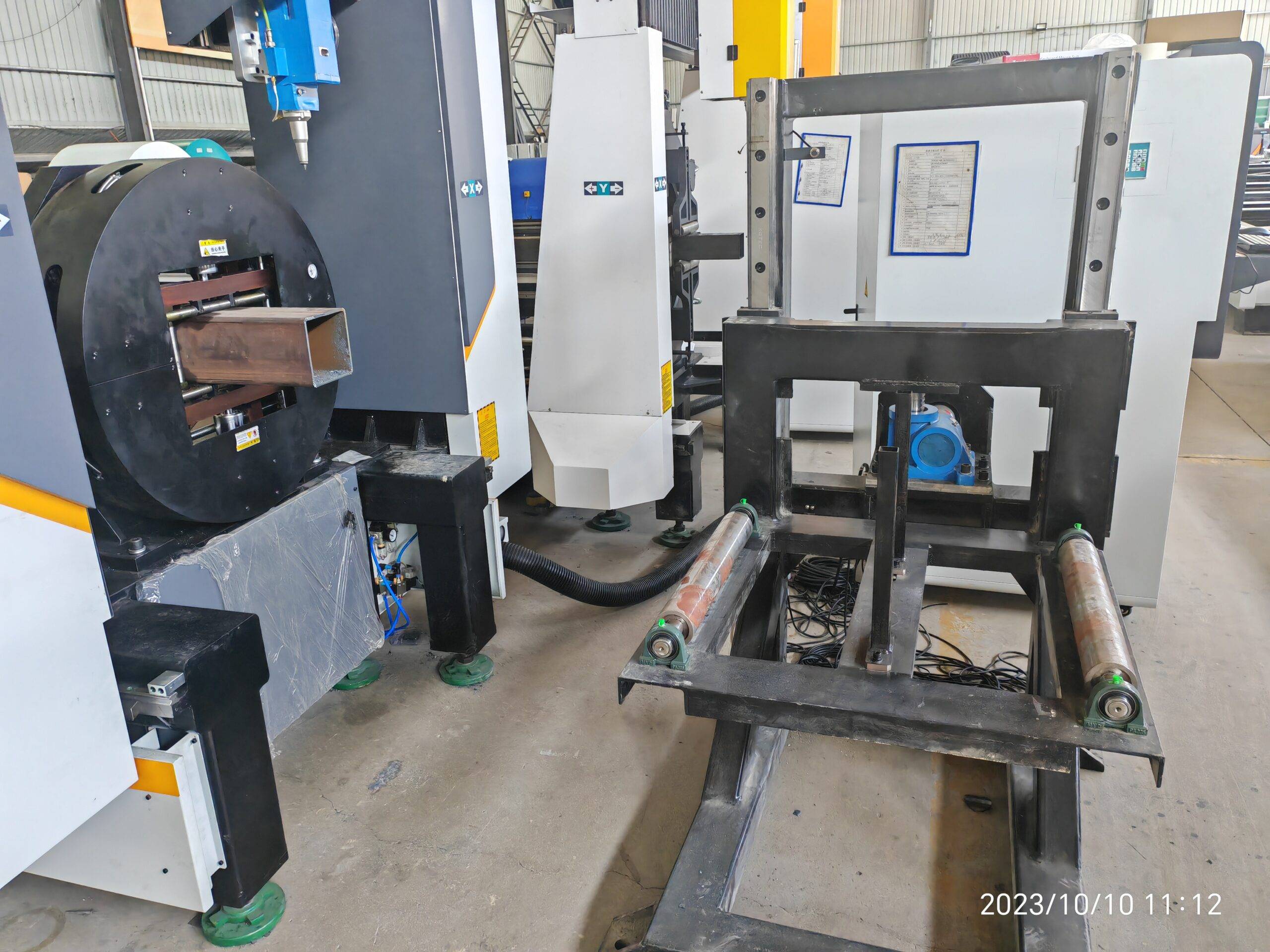
Pneumatic Chuck Clamping Dynamics, Rotary Axis Synchronization, and Thin-Wall Deformation Control in Micro-Component Tube Laser Processing
When we talk about achieving a minimum kerf width tube laser for micro engineering components, the conversation immediately leaves the realm of standard profile cutting and enters a domain governed by micron-level tolerances and the physics of material instability. Over two decades on the shop floor, I have seen more micro-component scrap piles generated by clamping error and thermal distortion than by laser power instability. For components like fuel injector nozzles (SUS304, wall thickness 0.3 mm) or miniature hydraulic valve sleeves (Al6061-T6, 0.5 mm wall), the kerf width target is often below 40 microns. Achieving this requires a holistic re-engineering of the workholding and motion system, not just a better resonator.
Pneumatic Chuck Clamping Dynamics: The First Point of Failure
Standard three-jaw chucks are the enemy of thin-wall micro tubes. The radial clamping force, typically delivered by a pneumatic cylinder at 0.4 to 0.6 MPa, creates a polygonal deformation pattern on the tube OD. For a 6 mm OD tube with a 0.3 mm wall, a clamping force of 800 N can induce a radial runout of 15-20 microns at the chuck face. This runout propagates along the Z-axis, causing the focal point of the laser to drift relative to the tube surface. The result is a kerf width that varies by 10-15 microns along the cut path.
For micro-engineering, we have moved to segmented collet chucks with a dedicated pneumatic circuit operating at a lower, precisely regulated pressure—typically 0.25 to 0.35 MPa for thin-wall SUS304. The chuck body is designed with a mechanical stop that limits the collet closure travel to 0.1 mm beyond the tube OD. This prevents over-clamping. The pneumatic circuit must include a proportional pressure regulator with a feedback loop to the CNC, compensating for any pressure drop during the rotary axis acceleration. On a recent retrofit for a medical stent laser cutter, we reduced the clamping pressure from 0.5 MPa to 0.28 MPa, which cut the radial runout from 18 microns down to 4 microns.
Rotary Axis Synchronization and Backlash Compensation
The rotary axis (C-axis) must be synchronized with the linear Z-axis to maintain a constant focal point on a helical cut path. The critical parameter here is the acceleration jerk profile. For a micro-component with a 2 mm cut length, the rotary axis might need to accelerate from 0 to 3000 RPM in 0.1 seconds. If the servo loop has a position lag of more than 2 encoder counts (typically 0.5 arc-seconds per count), the laser spot will trace an ellipse rather than a circle, widening the kerf on one side.
We use direct-drive torque motors on the C-axis, eliminating gear backlash. The encoder resolution must be at least 20-bit, and the servo update rate should be 16 kHz or higher. The synchronization algorithm must account for the tube’s bending moment during acceleration. For a 1.5 mm OD Al6061 tube, the torsional wind-up at 2000 RPM is roughly 0.02 degrees per meter. If the software does not compensate for this, the kerf width at the far end of the cut can increase by 8-10 microns due to the angular misalignment of the cut front.
Thin-Wall Deformation Control and Kerf Width Correlation
Thermal deformation is the second major contributor to kerf width instability. When the laser pierces a thin wall, the heat-affected zone (HAZ) creates a local expansion. If the clamping is too rigid, the material buckles. If too loose, the tube vibrates. The solution is a variable clamping force profile synchronized with the laser firing sequence. For a 0.4 mm wall SUS304 tube, we program the chuck to release clamping force by 15% during the 50 ms pierce phase, then re-apply full pressure for the cut. This is controlled via a high-speed pneumatic valve with a response time under 10 ms.
The gas delivery parameters are equally critical. For micro kerfs, we use a nitrogen assist gas at 1.2 MPa for stainless steel and 1.5 MPa for aluminum. The nozzle standoff must be maintained at 0.3 mm ± 0.02 mm. Any deviation increases the gas jet divergence, which erodes the kerf edge and widens the cut. On a production run of 10,000 micro-gears from 3 mm OD S355JR tube, we measured an average kerf width of 38 microns with a standard deviation of 2.1 microns using this method. The previous plasma cutting method yielded a kerf of 180 microns with a deviation of 25 microns.
Comparative Technical Data: Kerf Width and Process Stability
| Parameter | Conventional Plasma Cutting (Ar/N2 mix) | Mechanical Sawing (HSS Blade) | Fiber Laser (1.5 kW, 1070 nm) with Optimized Chuck |
| :— | :— | :— | :— |
| **Minimum Kerf Width (6 mm OD x 0.5 mm wall SUS304)** | 180 – 250 µm | 350 – 500 µm (blade thickness) | 35 – 45 µm |
| **Kerf Width Variation (3σ)** | ± 35 µm | ± 60 µm | ± 3.5 µm |
| **Heat Affected Zone (HAZ) Depth** | 150 – 300 µm | 0 µm (mechanical) | 15 – 25 µm |
| **Tube Wall Deformation (after cut)** | 0.05 – 0.15 mm ovality | 0.02 – 0.08 mm burr height | < 0.005 mm ovality |
| **Cut Speed (2 mm length, 0.5 mm wall)** | 0.8 sec | 2.5 sec (plus deburring) | 0.4 sec |
| **Pneumatic Chuck Pressure Required** | 0.6 MPa (standard) | N/A (mechanical clamp) | 0.28 MPa (segmented collet) |
| **Rotary Axis Synchronization Error** | N/A (stationary cut) | N/A | < 1 arc-second |
Real-World Implementation: The Micro-Nozzle Case
Consider a production run of 0.8 mm ID fuel nozzles from SUS304 tube, 8 mm length, 0.4 mm wall. The specification demanded a kerf width of 45 µm ± 5 µm. The initial setup used a standard pneumatic chuck at 0.5 MPa. The first 200 parts showed a kerf width ranging from 42 to 58 µm. The root cause was identified as a 12 µm radial runout at the chuck face, combined with a 0.03-degree angular misalignment between the C-axis and Z-axis during acceleration. We replaced the chuck with a segmented collet system, reduced pressure to 0.3 MPa, and re-calibrated the rotary axis backlash compensation table. The subsequent run of 5,000 parts yielded a kerf width of 44.2 µm with a standard deviation of 1.8 µm. The scrap rate dropped from 18% to 0.4%.
The laser parameters were also tuned: a pulse frequency of 20 kHz with a 40% duty cycle, peak power of 1.2 kW, and a nitrogen pressure of 1.3 MPa. The focal point was set 0.2 mm below the tube surface to account for the slight beam divergence through the thin wall. The combination of mechanical precision and laser pulse control is what defines the minimum achievable kerf width for micro-engineering components.
Industrial B2B Procurement FAQ
1. What is the maximum tube wall thickness I can process while maintaining a kerf width under 50 microns?
For SUS304, the practical limit is 0.8 mm wall thickness. Beyond that, the thermal conductivity of the material causes the kerf to widen as the laser power must be increased to maintain cut speed. For Al6061, the limit is 1.0 mm. For carbon steel (S355JR), you can go up to 1.2 mm wall thickness with a kerf width of 45-55 microns, provided you use a nitrogen assist gas at 1.5 MPa and a segmented chuck with < 5 micron runout.
2. How do I verify the rotary axis synchronization accuracy before production?
Use a laser interferometer with a rotary axis kit. Mount a precision mirror on the chuck face. Run a 360-degree sweep at the intended cutting RPM (e.g., 2000 RPM). The allowable angular deviation should be less than 2 arc-seconds. Then perform a cut test on a 10 mm long tube section with a helical path. Measure the kerf width at the start, middle, and end. If the variation exceeds 5 microns, the synchronization lag or chuck runout is unacceptable.
3. What is the recommended maintenance cycle for the pneumatic chuck system in micro-kerf applications?
Inspect the collet segments for wear every 200,000 cycles. Replace the pneumatic pressure regulator filter element every 3 months. Calibrate the proportional pressure valve output against a digital pressure gauge every 500 hours of operation. The most common failure mode is a 0.02 MPa drift in the regulator output, which can increase clamping force by 15% and cause tube deformation. Log the chuck runout using a dial indicator monthly; if it exceeds 8 microns, re-grind the collet faces.













