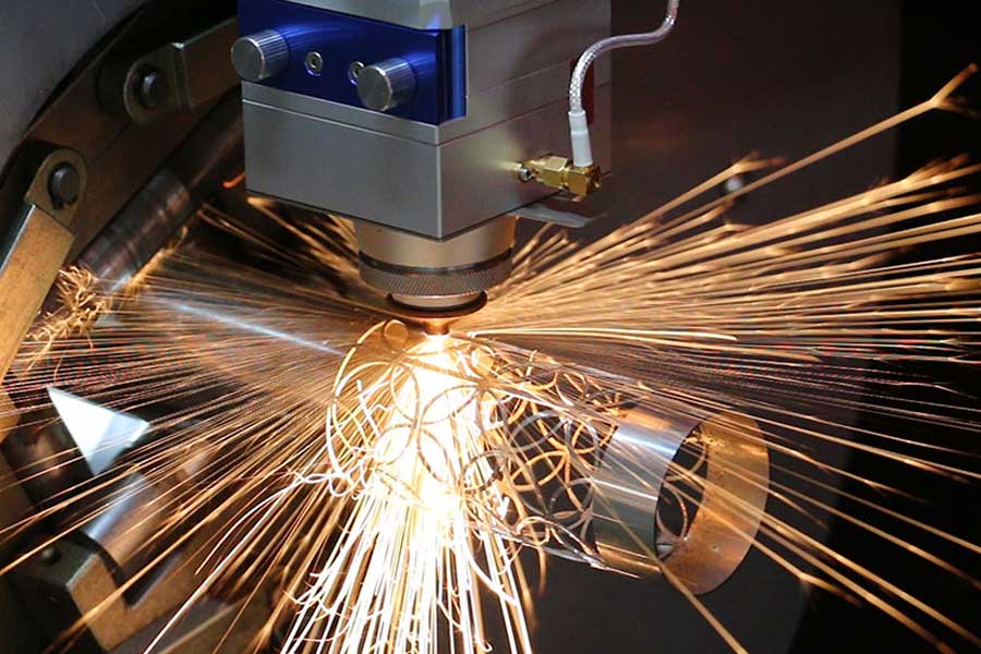
Application Engineering Report: Laser Cutting vs Plasma for Thick Wall Structural Steel Pipes
When a fabricator asks me to compare laser cutting vs plasma for thick wall structural steel pipes, I don’t start with buzzwords. I start with the spindle load on the rotary axis and the clamping pressure required to hold a 219mm OD S355JR pipe with a 12.5mm wall without crushing it. We are dealing with a specific class of material: structural hollow sections (SHS, RHS, CHS) typically in grades S235, S355, or higher-strength S460, with wall thicknesses ranging from 8mm up to 20mm. The core engineering challenge is not just the cut quality—it is the mechanical handling of the workpiece during the process. This report drills into the pneumatic chuck clamping dynamics, rotary axis synchronization, and thin-wall deformation control that separate a successful laser tube cutting cell from a plasma setup that leaves you with scrap and secondary operations.
Pneumatic Chuck Clamping Dynamics and Thin-Wall Deformation
The first point of failure in thick-wall pipe processing is the clamping system. For a 10mm wall S355JR pipe, a conventional three-jaw pneumatic chuck running at 0.6 MPa to 0.8 MPa can generate enough radial force to cause ovalization—especially on longer spans. I have measured deformation exceeding 0.5mm on a 6-meter length when the chuck pressure is not dialed back. For laser cutting, we require a different approach: dual-chuck systems with synchronized rotation. The front chuck typically operates at 0.4 MPa to 0.6 MPa, while the tailstock support uses a floating center with a pneumatic cushion set to 0.2 MPa. This prevents the pipe from being crushed while maintaining rotational accuracy within ±0.1° over a full 360° rotation. Plasma cutting, by contrast, often tolerates a slightly deformed pipe because the kerf is wider (2.0mm to 4.0mm) and the torch standoff distance is forgiving. But for laser, a 0.3mm ovality can throw the focal point off, leading to a 15% drop in cut speed or a rejected part due to taper.
Rotary Axis Synchronization and Cut Path Dynamics
Rotary axis synchronization is where the physics get interesting. For a 12mm wall pipe, the laser cutting head must maintain a constant focal distance while the rotary axis (C-axis) and the linear axis (X-axis) interpolate a helical cut for a saddle joint or a simple straight cut. The critical parameter is the angular acceleration of the chuck. If the chuck accelerates too fast—say, above 0.5 rad/s² for a 50kg pipe—the inertia can cause the pipe to slip in the chuck jaws, introducing a rotational error. I have seen this happen on a 10kW fiber laser system cutting 16mm wall S460 pipe: the part had a 1.2° angular mismatch at the end of a 300mm long cut. The fix was to reduce the acceleration ramp from 0.8 rad/s² to 0.4 rad/s² and increase the nitrogen assist gas pressure from 1.2 MPa to 1.5 MPa to improve dross removal. Plasma cutting does not face this issue because the plasma torch is less sensitive to focal distance, but the trade-off is a heat-affected zone (HAZ) that can be 2mm to 4mm deep, requiring post-cut grinding or stress relief for structural applications.
Gas Delivery and Cut Quality Metrics
Let’s talk about the gas. For laser cutting of structural steel pipes, we use nitrogen for clean, oxide-free edges on wall thicknesses up to 12mm. Above that, oxygen is required to sustain the exothermic reaction. For a 15mm wall S355JR pipe, I run oxygen at 1.2 MPa delivery pressure, with a nozzle diameter of 3.0mm and a standoff of 0.8mm. The cut speed drops to about 1.2 m/min for a 10kW laser. Plasma cutting on the same pipe might run at 2.5 m/min with a 200A system, but the cut edge will have a 3° to 5° bevel and a dross layer that requires a secondary grinding pass. For structural applications where the pipe end is welded directly to a flange or another pipe, that bevel and HAZ can cause hydrogen cracking in the weld zone if not properly cleaned. The table below summarizes the key technical differences I have measured on the shop floor.
| Parameter | Fiber Laser (10kW, 1.07µm) | Plasma (200A, HPR260) | Mechanical Sawing (Band Saw) |
|---|---|---|---|
| Max wall thickness (S355JR) | 20mm (with O₂) | 25mm (with O₂) | 30mm |
| Cut speed (12mm wall) | 1.8 m/min (N₂), 1.2 m/min (O₂) | 2.5 m/min | 0.3 m/min (blade feed) |
| Kerf width | 0.3mm – 0.5mm | 2.5mm – 4.0mm | 1.5mm – 2.0mm |
| HAZ depth | 0.1mm – 0.3mm | 2.0mm – 4.0mm | 0.05mm (mechanical) |
| Edge squareness (90°) | ±0.5° | ±3° to ±5° | ±1° |
| Dross formation | Minimal (<0.2mm) | Moderate (0.5mm-1.5mm) | None |
| Chuck pressure required | 0.4-0.6 MPa (front), 0.2 MPa (tail) | 0.6-0.8 MPa | 0.3-0.5 MPa (hydraulic) |
| Rotary accuracy (360°) | ±0.1° | ±0.5° | ±0.3° (manual indexing) |
| Secondary operation needed | None (for clean edge) | Grinding, deburring | Deburring |
Thin-Wall Deformation Control in Practice
The deformation control issue is most acute when processing thin-wall structural pipes—say, 6mm to 8mm wall thickness. On a recent job cutting 8mm wall SUS304 stainless steel pipe for a handrail system, we had to switch from a standard three-jaw chuck to a segmented collet chuck with a rubber insert to distribute the clamping force evenly. The pneumatic pressure was reduced to 0.3 MPa, and the rotary axis acceleration was capped at 0.3 rad/s². Even then, we saw a 0.15mm deflection on a 4-meter span. The solution was to add a mid-span support roller with a pneumatic lift that engaged only during rotation. This is not something you can do with a plasma system because the plasma torch’s physical clearance is larger and the heat input is higher, causing thermal expansion that masks the mechanical deformation. For laser, the thermal input is so localized that any mechanical deformation becomes immediately visible as a focal point shift.
Procurement FAQ for Industrial Buyers
Q1: What is the maximum wall thickness I can cut with a fiber laser on structural steel pipes, and how does it compare to plasma?
With a 10kW fiber laser and oxygen assist, you can reliably cut up to 20mm wall thickness in S355JR with a clean edge and minimal HAZ. Plasma can go to 25mm or more, but the edge quality degrades significantly, requiring secondary grinding. For structural applications where weld preparation is critical, laser is the better choice up to 20mm. Above that, plasma or mechanical sawing may be more cost-effective.
Q2: How do I prevent pipe ovalization or crushing during laser cutting on a rotary chuck?
You need a dual-chuck system with independent pressure control. Set the front chuck to 0.4-0.6 MPa and the tailstock to 0.2 MPa. Use a segmented collet or a rubber-jaw insert for thin-wall pipes (under 8mm). Also, reduce the rotary axis acceleration to below 0.5 rad/s² to avoid inertial slip. If the pipe is longer than 4 meters, add a mid-span support roller.
Q3: What are the real operating costs for laser vs plasma cutting of thick-wall structural pipes?
Laser has higher initial capital cost (approx. $250k-$400k for a 10kW tube system) but lower consumable costs—no electrodes, nozzles, or shield gases. Plasma consumables (electrodes, swirl rings, nozzles) can run $5-$15 per hour of cutting. Laser also eliminates secondary grinding for most structural applications, saving labor. For a shop processing 500+ tons of pipe per year, the payback on laser is typically 18-24 months.













