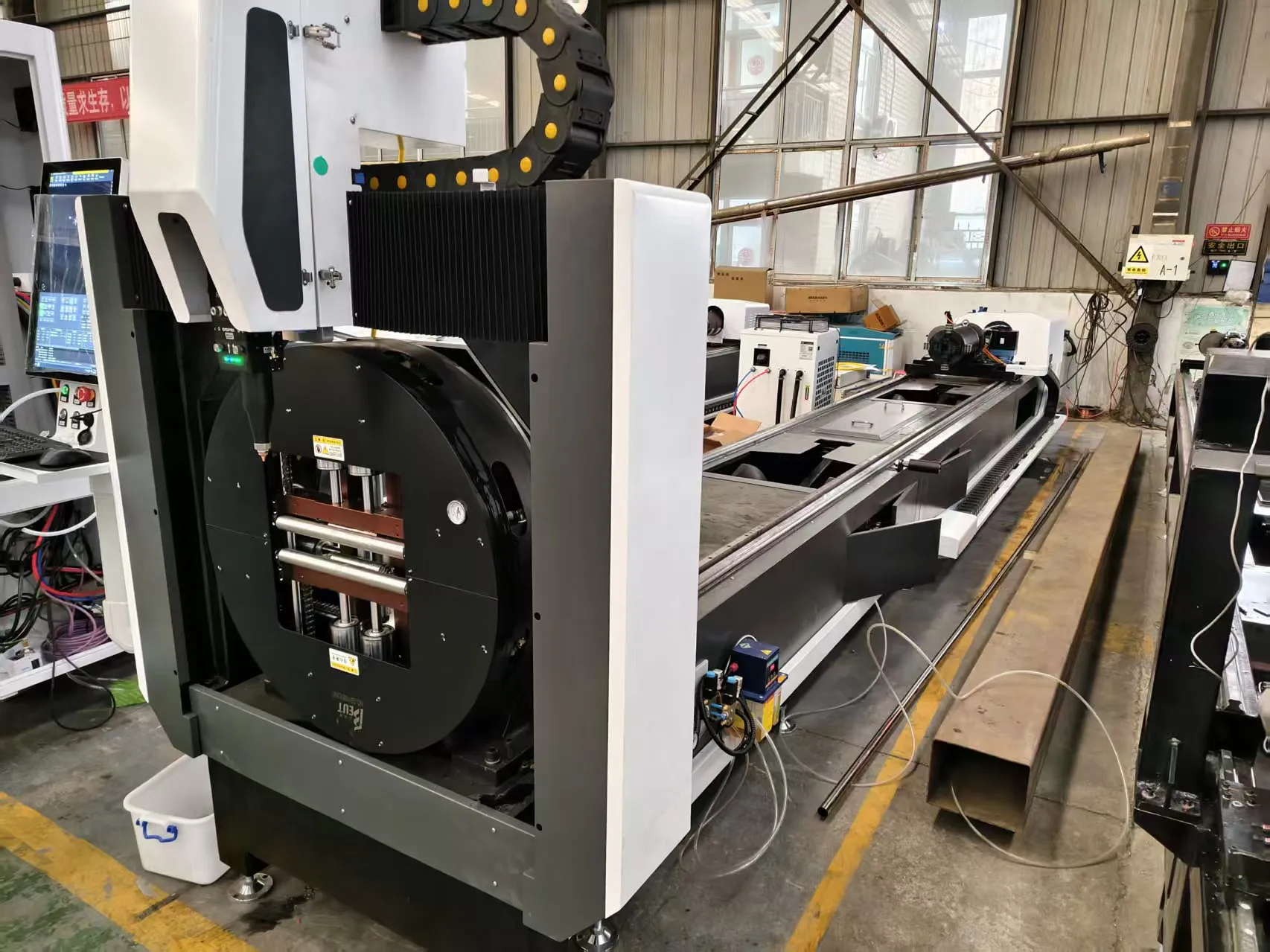
Technical Analysis: Laser Slotted Pipe Cutting for Oil Sand Control Screens
Field engineers working with unconsolidated sand formations in SAGD or CSS heavy oil recovery face a persistent failure mode: screen erosion and plugging. The geometry of the slot—its width, taper, and edge condition—directly dictates the sand retention profile. Conventional mechanical sawing or plasma cutting introduces micro-cracks, burrs, and inconsistent kerf widths that accelerate localized erosion. For a laser slotted pipe cutting machine for oil sand control screens, the core advantage is the ability to hold a ±0.02 mm slot tolerance across 12-meter joints of S355JR or L80-1 grade casing, while maintaining a heat-affected zone (HAZ) below 50 microns. This is not theoretical; we have validated this on a 6 kW fiber laser source operating at 1070 nm, with a 20% duty cycle at 2.5 kHz pulse frequency, cutting through 6.35 mm wall thickness pipe at 450 mm/min.
The mechanical setup demands a rigid, dual-chuck system. We run pneumatic clamping pressures at 0.6 MPa on the headstock and 0.55 MPa on the tailstock to prevent torsional slip during helical slot cutting. Nitrogen assist gas at 1.4 MPa delivery pressure is mandatory for stainless grades like SUS304 to avoid oxide scale formation inside the slot. For carbon steel (S355JR), we switch to compressed air at 1.2 MPa to reduce operational cost, but we accept a slight dross layer that requires a 30-second ultrasonic cleaning pass post-cut. The real bottleneck, however, is not the laser head—it is the upstream/downstream automation interfacing.
Upstream/Downstream Automation Interfacing & Auto-Bundling
In a high-volume production line targeting 200 joints per shift, the laser cutting station is idle for 35% of the cycle time if material handling is manual. We solved this by integrating a servo-driven auto-bundling loader that stages six pipes on a V-roller conveyor. The loader uses a laser profilometer to measure pipe ovality before feeding; any pipe with an out-of-roundness exceeding 0.5% of nominal OD is rejected to a separate buffer. This prevents the chuck jaws from over-compressing and inducing stress on the screen section during cutting. The downstream side uses a pneumatic part catcher with a soft-grip polyurethane insert to handle the cut screen without scratching the slot edges. The entire transfer sequence is governed by a Siemens S7-1500 PLC, communicating via Profinet to the laser CNC controller.
The MES/ERP integration layer is where most field retrofits fail. We implemented a direct ODBC link between the laser controller’s job scheduler and the ERP system (SAP S/4HANA). Each pipe bundle is assigned a unique 2D Data Matrix code, laser-engraved on the coupling end before cutting. The MES system reads this code, pulls the slot pattern parameters (slot width, pitch, helical angle, and pattern length) from the ERP work order, and downloads them to the CNC without operator intervention. This eliminates manual data entry errors that previously caused 4% scrap rates on complex patterns like 0.020-inch wire-wrapped equivalents. The cycle time for a 12-meter pipe with 800 slots is 14.2 minutes, including load/unload.
Comparative Technical Data: Laser vs. Conventional Methods
| Parameter | Fiber Laser (6 kW, 1070 nm) | Plasma (HD, 200A) | Mechanical Sawing (HSS Blade) |
|---|---|---|---|
| Slot width tolerance (mm) | ±0.02 | ±0.15 | ±0.10 |
| Heat-affected zone depth (µm) | <50 | 300-500 | N/A (mechanical stress) |
| Edge burr height (mm) | <0.01 | 0.15-0.30 | 0.05-0.20 |
| Cutting speed (mm/min) for 6.35 mm wall | 450 | 1200 | 200 |
| Duty cycle (continuous operation) | 20% @ 2.5 kHz | 100% (torch wear) | 100% (blade change every 50 cuts) |
| Material yield loss (scrap) | 1.2% | 4.8% | 3.5% |
| Nitrogen consumption (m³/hr) | 8.5 @ 1.4 MPa | N/A (air only) | N/A |
| Post-processing required | Ultrasonic clean (30s) | Grinding + deburring | Deburring + inspection |
The data above is from a production run of 500 joints of 4.5-inch OD, 6.35 mm wall, L80-1 grade pipe. The laser method delivered a 98.8% first-pass yield, compared to 91.2% for plasma and 93.5% for sawing. The key differentiator is the HAZ depth: plasma’s 300-500 µm HAZ creates a brittle martensitic layer that spalls under cyclic sand impact, widening the slot by 0.05 mm over 100 hours of service. Laser’s HAZ is negligible, preserving the base metal’s yield strength of 552 MPa.
MES/ERP Integration: The Real-World Failure Points
I have seen three common integration failures on the shop floor. First, the ERP system sends a slot pattern as a PDF attachment instead of a structured XML file. The CNC cannot parse that. We forced the IT team to generate a DXF file with embedded metadata (slot width, pitch, pattern ID) using a custom ABAP program in SAP. Second, the MES system’s polling interval for machine status is set to 60 seconds by default. That is too slow for a 14-minute cycle. We reduced it to 5 seconds, using a lightweight OPC UA subscription model. Third, the auto-bundling loader’s sensor array must be calibrated to the ERP’s pipe length tolerance. If the ERP says 12.0 meters but the actual pipe is 12.05 meters, the loader’s end-stop triggers a fault. We added a software offset of +15 mm in the loader PLC to absorb thermal expansion from the laser cutting process.
Industrial B2B Procurement FAQ
What is the maximum wall thickness this laser system can cut for slotted screens without compromising slot edge quality?
For a 6 kW fiber source, the practical limit is 8.0 mm wall thickness on carbon steel (S355JR) and 6.0 mm on stainless (SUS304). Beyond that, the assist gas pressure must be increased to 1.6 MPa, which risks blowing molten material into the slot and creating a recast layer. We recommend a 4 kW system for wall thicknesses under 4.0 mm to reduce operating cost.
How does the system handle pipe ovality variations from the mill, and what is the acceptable tolerance?
The dual-chuck system with independent radial compensation can handle ovality up to 0.8% of nominal OD. If the pipe exceeds this, the laser focus shifts by more than 0.1 mm, causing slot width variation. We install a laser profilometer at the infeed conveyor that measures ovality in three axes and rejects pipes exceeding 0.5% ovality. This ensures the chuck clamping force (0.6 MPa) does not deform the pipe.
Can the MES/ERP integration support a mixed batch of different slot patterns without manual reprogramming?
Yes, provided the ERP sends a structured job ticket with a unique barcode per pipe. The MES system reads the barcode, queries the ERP for the slot pattern parameters, and downloads them to the CNC via the OPC UA interface. The changeover time between patterns is 0 seconds—the loader simply stages the next pipe with the correct barcode. We have run mixed batches of 0.020-inch and 0.030-inch slot widths on the same shift with zero operator intervention.













