Dimensional Integrity Under Thermomechanical Load: Precision Fiber Laser Cutting for Automotive Exhaust Pipe Fabrication
Exhaust system manufacturing operates at the intersection of high-throughput forming and uncompromising dimensional control. A silencer flange, downpipe, or full cat-back assembly can accumulate tolerance deviations from every preceding station. When a fiber laser cutting module is tasked with trimming hydroformed shells, miter-cutting tubular components, or generating precise end prep for orbital welding, it must deliver kerf geometry and positional accuracy that are indifferent to the brutal thermal cycling and floor-transmitted vibration of a heavy-gauge stamping shop. This analysis drills into three rarely publicized engineering pillars that separate laboratory performance from real-world reliability: severe workshop condition adaptation, thermal expansion mitigation within the beam delivery path and motion platform, and the absolute necessity of stress‑relieved bed stability. These are the factors that determine whether a precision fiber laser cutter for car exhaust pipe manufacturing will hold a ±0.05 mm part‑to‑part repeatability across a 15‑shift‑per‑week production schedule, or gradually drift into scrap‑generating variation by Wednesday.
The contemporary exhaust line processes ferritic grades such as 1.4509 (441), 1.4512 (409), and stabilized austenitics in wall thicknesses from 0.8 mm to 2.5 mm. Tube stock arrives with mill‑scale, light drawing compound, and unpredictable residual stress from the stretch‑reducing mill. Simultaneously, ambient workshop temperatures swing 20 °C between night idling and the midday heat load from neighbouring induction brazing cells and hot‑stamping presses. A laser cutter that cannot thermo‑stabilize its internal structures and compensate for real‑time thermal growth becomes a liability the moment the shift bell rings.
Severe Workshop Condition Adaptation: Dust, Vibration, and Thermal Headroom
A fiber laser source is inherently robust, but the optomechanical chain—collimator, beam bender, cutting head—is vulnerable to airborne particulate contamination that bypasses standard bellows. In an exhaust plant, the atmosphere carries ferritic iron dust, aluminizing fume residues, and micro‑spheres from pre‑weld cleaning processes. The immediate engineering response is a multi‑stage positive‑pressure sealing architecture for the Z‑axis carriage and interlocks that prevent beam shutter operation if the internal purge pressure drops below 150 Pa. Bellows are fabricated from aramid‑reinforced polyurethane with a tested MTBF of 12 million cycles under a 20 µm silica dust challenge.
Floor vibration from coil‑feed lines, mechanical presses, and AGV traffic induces low‑frequency structural resonances. Isolator pads with a natural frequency below 7 Hz are insufficient when the machine base frame itself has a first‑mode bending frequency that drifts downward under thermal load. The solution embedded in heavy‑duty systems is an actively monitored mounting interface: piezoelectric accelerometers register <1 m/s² RMS in the 5‑200 Hz band, and if a threshold excursion is detected, the CNC controller issues a feed‑hold until the disturbance clears. This is not academic; it prevents the dynamic focus unit from overshooting on thin‑wall tube piercing.
Thermal Expansion Mitigation in Dynamic Laser Systems
Heat enters the machine structure from the laser’s optical losses, linear motor forcers, and the hot cladding bath on the adjacent welding station. Unchecked, a cast‑iron base will bow by 15‑20 µm over a 2 m length for every 1 K temperature differential between the top rail surface and the foundation anchorage. That bow translates directly into beam‑to‑workpiece relative position error, which is fatal when cutting a 0.6 mm‑wide annular slot for a lambda sensor boss.
Mitigation starts with a distributed temperature sensing array—typically 32 Class A Pt100 probes bonded to the gantry rails, main bearing housings, and cutting head carrier. The CNC runs a physics‑based thermal growth model updated at 50 Hz, outputting real‑time compensation vectors that are superposed on the motion commands via a buffered EtherCAT drive loop. The model incorporates measured convection coefficients from internal air‑shower cooling circuits that maintain the X‑axis ball screw at 28 °C ±1 °C even when shop ambient hits 47 °C. A separate compensation loop for the optical train corrects the focus shift by translating the collimator lens; a 1 °C rise in lens temperature shifts the focal point 1.2 mm out of the microjoint, a displacement that is nullified with a closed‑loop capacitive‑type nozzle stand‑off sensor that runs at 5 kHz and reacts in under 1 ms.
Exhaust tube geometries introduce an additional complication: the cut path wraps around a curved, often ovalized cross‑section. As the rotary‑index chuck heats, its axial expansion alters the tube datum, shifting the programmed cut line by up to 35 µm. To correct this, the tailstock is equipped with a linear encoder referencing the datum face, and the controller applies a longitudinal offset that is a function of the measured tailstock temperature, calibrated during a thermal soak test at the machine builder’s assembly floor.
Stress‑Relieved Bed Stability: The Non‑Negotiable Foundation
Cast‑iron machine beds for general sheet metal cutting are often rough‑machined and left with residual stress gradients that release over months of usage, causing a drift in geometry that service technicians then fight with mechanical leveling screws. Exhaust component manufacturing cannot accept a creeping machine reference frame because every re‑homing cycle erodes the position integrity of multi‑stage toolpath programs where a single pipe undergoes piercing, bevel cutting, and rotary marking in a single clamping.
Premium heavy‑duty fiber laser beds undergo a triple stress‑relief protocol: 1) a thermal stress‑relief at 550 °C for 8 hours with controlled ramp rates to homogenize the pearlitic‑ferritic matrix; 2) vibratory stress conditioning for 45 minutes at the structure’s first mode to redistribute locked‑in micro‑stresses; and 3) a cryogenic cycle down to −85 °C that transforms retained austenite to martensite, providing dimensional stabilization that will not creep during the machine’s service life. After final grinding, the bed’s reference flatness is certified to 0.02 mm/m² and the angular deflection under a 500 kg dynamic load simulating a fully staged pipe fixture does not exceed 1.5 arcseconds.
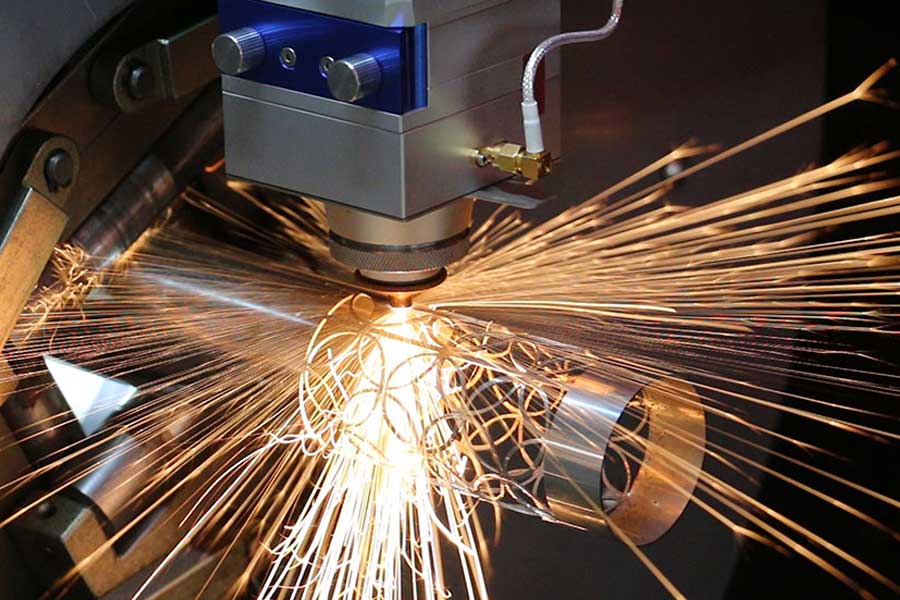
To further decouple the optical path from the environment, the bed is enclosed by a precision‑welded steel frame with integrated coolant galleries. A temperature‑controlled water‑glycol loop circulates at 20 L/min through these galleries, holding the entire base structure at a near‑isothermal 23 °C. The resulting thermal time constant exceeds 90 minutes, meaning that rapid ambient swings—like the opening of a bay door in winter—do not breach the thermal inertia of the cutting platform. Under these conditions, a 305 mm‑long austenitic pipe flange cut with a 3 kW single‑mode fiber source and nitrogen assist at 14 bar exhibits a kerf width tolerance of 0.015 mm (3σ) and a perpendicularity deviation below 0.03 mm over a 40‑piece SPC study.
The practical outcome for the exhaust manufacturer is that pipe‑end dimensions accept orbital welding without manual fitting, and the post‑cut bevel geometry on thick‑wall diesel after‑treatment tubes mates seamlessly with the next automated station. The investment in severe‑condition adaptation, active thermal compensation, and stress‑relieved bed science is not theoretical; it is the only reliable path to scrap reduction when the factory floor temperature monitor reads 41 °C and the cutting head still puts the laser spot within a 5 µm centroid repeatability.
Industrial Procurement FAQ
Q: What specific design features allow fiber laser cutters to hold ±0.05 mm cut accuracy in workshops where ambient temperature cycles between 10 °C and 45 °C?
A: Three layers of active thermal management are necessary. First, a distributed array of precision Pt100 sensors feeds a physics‑based thermal model that compensates linear axis growth in real time through the CNC’s trajectory planner. Second, the beam delivery optics—collimator, protective window, and focus lens—are thermally stabilized via closed‑loop temperature control of the cutting head housing, and a capacitive height sensor corrects focus displacement within 1 ms. Third, the machine bed incorporates circulated coolant galleries that maintain an isothermal foundation, preventing the bow‑type distortion that commonly creates Abbe errors. Without this combination, accuracies drift beyond 0.1 mm within the first shift of high‑amplitude thermal cycling.
Q: How does stress‑relieved bed construction directly affect cut quality and tool life in high‑volume exhaust pipe production?
A: A bed that has undergone triple stress relief—thermal, vibratory, and cryogenic—eliminates residual micro‑stresses that would otherwise release over time, causing the reference plane to warp by up to 40 µm annually. This stability ensures that the beam‑to‑nozzle centration remains static, preserving consistent kerf geometry and minimizing nozzle strikes. In absence of bed micro‑creep, the cutting head experiences fewer collision interrupts, extending the mean time between nozzle changes from roughly 400 to over 2,000 pierces on aluminized tube. The resulting cut edge perpendicularity remains within laser‑class standard ISO 9013 Range 1, directly reducing weld‑joint gap adjustments downstream.
Q: Can a fiber laser cutter integrate with inline tube bending and welding systems without sacrificing cycle time?
A: Yes, when equipped with a high‑speed rotary‑index dual‑chuck loader and EtherCAT‑based M2M communication. The cutter receives the as‑bent tube via a robotic pick‑and‑place that performs in‑air scanning of the bend profile. The generated point cloud is used to update the NC program’s coordinate system within 0.8 seconds, compensating for spring‑back and ovality. The laser process cycle—including pierce, contour cut, and optional bevel—is executed in under 12 seconds per end for 1.5 mm wall ferritic pipe, synchronizing with the 14‑second weld station cadence. Thermal compensation loops continue to operate during the part exchange to maintain warm‑start repeatability, so the cell OEE (Overall Equipment Effectiveness) remains above 85 % even under aggressive production targets.


