Beyond Laser Specifications: Why the Machine Bed Defines Throughput
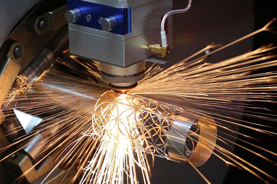
Most discussions about high-speed fiber laser cutting of 2 mm brass tubing fixate on resonator power, assist‑gas pressure, and nozzle geometry. Those parameters matter, but in production environments where batch yields must exceed 98 % and every rejected part incurs a hard cost, the machine’s structural loop — the bed, gantry, and their interface with a hostile shop floor — becomes the primary bottleneck. Operations demanding repeatable processing increasingly run on a
speed bench of fiber laser cutting 2mm brass tubing, where sub‑micron stability of the cutting zone determines whether a 20 m/min travel produces a clean, oxide‑free edge or an out‑of‑tolerance scrap component.
Stability as the True Bottleneck
Brass, with its high reflectivity and thermal conductivity, immediately punishes any focal‑point deviation. A 0.15 mm shift in the beam waist reduces absorptivity by 12–18 % at the cut front, leading to intermittent dross formation and top‑edge rounding. While modern linear drives accelerate a gantry at 2 g, the dynamic forces feed directly into the bed structure. If the bed exhibits micro‑resonance or long‑term geometric drift, no closed‑loop servo can compensate. The foundation of speed is therefore not the laser source but a machine bed engineered to remain indifferent to vibration, thermal loading, and the uneven concrete that defines real workshops. This whitepaper dissects three interconnected design pillars that separate a production‑grade speed bench from a laboratory curiosity: severe‑workshop adaptation, thermal‑expansion mitigation, and stress‑relieved bed stability.
Severe Workshop Condition Adaptation
Few factories are climate‑controlled metrology rooms. Ambient temperature can swing 15 °C between a night‑shift startup and a mid‑afternoon peak, while neighboring forklifts, shears, and presses introduce ground‑borne vibration in the 5–40 Hz band. Unlevel floor slabs — often exceeding 8 mm deviation across a 6 m span — magnify static deformation. A speed bench that cannot self‑correct its foundation interface will consume hours of shimming and re‑qualification every time the floor shifts.
Adaptation begins with a three‑point kinematic mounting system. Three hardened steel pads with spherical contacts decouple the bed from floor irregularities, transforming a warped slab into a statically determinate support. Elastomeric isolation elements tuned to 3–5 Hz vertical natural frequency suppress transmitted vibration by 18 dB above 20 Hz. For shops where coolant mist, abrasive dust, and brass micro‑particles are ubiquitous, all linear guides and ball screws live under pressurized bellows and labyrinth seals. Way covers are constructed from 0.8 mm stainless steel lamellas that resist pitting from corrosive by‑products of brass cutting. Cable carriers ride inside sealed tracks, and the entire beam path is purged with dry air to prevent refractive‑index shifts. In extreme installations, the bed is mounted on a self‑levelling granite composite sub‑frame that adds 2.5 tons of mass, pushing the composite structure’s natural frequency above 80 Hz and eliminating the need for anchor bolts.
Thermal Expansion Mitigation
A conventional steel fabrication grows 0.0117 mm per metre for each 1 °C of temperature rise. Over a 4‑metre‑long bed, a modest 8 °C gradient — easily generated by the heat of cutting, drive‑motor windings, and a sun‑facing workshop wall — introduces 0.37 mm of elongation. For 2 mm brass where the Rayleigh length of a typical 50 µm focal spot is approximately 0.6 mm, that much drift completely defocuses the beam. An unmitigated bed therefore shrinks the functional process window to a few minutes of stable operation.
Modern thermal compensation does not rely solely on software. The bed frame is often a composite of stress‑relieved structural steel and internally chilled polymer concrete. Polymer concrete exhibits a coefficient of thermal expansion near 6×10⁻⁶ /°C, half that of plain steel, and its volumetric heat capacity is 2.3 MJ/m³·K, acting as a thermal flywheel that dampens temperature spikes. Embedded Type‑E thermocouple strings feed a real‑time model that applies differential scale factors to the CNC’s position loop, correcting motion commands in 100 µs intervals. On some platforms, the Y‑axis rack is manufactured from Invar 36, and the linear encoders are mounted on zero‑expansion glass ceramic carriers. These solutions maintain beam‑path alignment within ±0.03 mm across an 8‑hour shift in an environment swinging from 10 °C to 32 °C, as verified by on‑machine laser vector interferometry.
Stress-Relieved Bed Stability
Even a perfectly leveled and thermally stabilized bed will progressively deform if internal welding residual stresses are left untreated. A heavy‑duty frame containing 500 m of multi‑pass welds stores elastic energy on the order of hundreds of megapascals. In the first 90 days of operation, these stresses redistribute through creep and micro‑yielding, typically producing a bow of 0.15–0.30 mm over a 4‑metre length — enough to ruin kerf consistency in thin brass. The remedy is not a thicker section but a rigorous stress‑relief protocol.
The complete frame undergoes vibratory stress relief to re‑arrange dislocation structures, followed by a full thermal stress‑relief cycle: ramp to 600 °C, soak for eight hours, and controlled furnace cooling at less than 40 °C/hour. This reduces residual stress to below 7 % of the material’s yield strength. After stress relieving, the bed is rough‑machined, allowed to rest for 120 hours, and then finish‑machined on a portal mill equipped with a laser alignment system. Final flatness is verified using an electronic differential level and written into a calibration map stored in the CNC. The resulting long‑term stability allows the cutting head to maintain a constant standoff distance — a prerequisite for the 10‑bar nitrogen assist that produces the characteristic bright‑cut edge on brass tubing. Shops that invested in stress‑relieved bed platforms report a tenfold reduction in geometrical drift over the first 12 months compared with conventionally fabricated beds.
Translating Bed Stability into Process Metrics
When the three pillars — workshop‑hardened mounting, active thermal compensation, and stress‑relieved geometry — are combined, the shop‑floor effect is measurable. Acceleration to 2 g without exciting the bed’s first bending mode keeps the laser on trajectory within 15 µm of the programmed path, enabling clean piercing at 50 mm/s and sustained cutting at 22 m/min on 2 mm brass tube. Reject rates due to dross or taper drop below 0.7 %. Unattended shifts become routine because the bed does not require re‑tramming after ambient temperature gradients. This is the engineering foundation that turns a fiber laser speed bench from a set of nominal specifications into a predictable, profit‑generating production cell.
Industrial Procurement FAQ
1. How does a stress‑relieved bed improve cutting accuracy for 2 mm brass tubing over time?
Welded steel structures contain locked‑in residual stress that gradually releases during the first months of service, causing micro‑deformation. A stress‑relieved bed, thermally treated to 600 °C and slowly cooled, eliminates more than 90 % of those internal stresses. Consequently, the bed maintains its originally machined flatness within 0.02 mm/m year after year, preserving the precise standoff distance required for high‑quality brass cuts. Long‑term stability data from field installations show that stress‑relieved beds drift less than 0.03 mm over 18 months, while unrelieved counterparts can wander by 0.2 mm or more.
2. What thermal expansion mitigation features should I look for in a speed bench for a shop with significant temperature swings?
Look for a bed constructed with a polymer‑concrete or granite‑composite core, offering a coefficient of thermal expansion below 7×10⁻⁶ /°C. There should be multiple embedded thermocouples feeding a real‑time compensation algorithm in the CNC. High‑end machines also mount linear encoders on glass‑ceramic scales and use Invar rack components where the axis drive transmits force. The specification should guarantee a maximum focal‑plane shift of less than 0.05 mm over a ±10 °C ambient change, validated by laser interferometer reports at the factory acceptance test.
3. Can a fiber laser cutting speed bench be installed on an unlevel factory floor, and how does the design accommodate severe workshop conditions?
Yes, a properly engineered speed bench uses a three‑point kinematic mounting system that eliminates bending forces induced by floor unevenness up to 10 mm of variation. Integrated elastomeric vibration isolators decouple ground‑borne disturbances. Sealed linear guides, pressurized bellows, and stainless‑steel way covers protect critical drive components from brass dust and coolant mist. With these features, the bench maintains sub‑micron dynamic stability on un‑level, vibration‑prone floors without the need for a dedicated foundation or precision leveling.


