1. The Material Integrity Frontier in Offshore Gas Transmission
Offshore gas pipeline construction hinges on the metallurgical discipline required to turn 12 to 18‑meter joints of API 5L X65/X70 grade line pipe into field‑ready spools, each carrying weld preps, pressure‑containment profiles, and corrosion‑allowance tolerances that a rough‑fit cutting torch cannot hold. The first layer of difficulty arrives with the pipe itself. A typical S‑lay or J‑lay campaign consumes thousands of joints, every one demanding a unique combination of bevel angles, counterbores, brace piercing cutouts, and anode‑attachment slots. When processing volumes cross the 500‑joint threshold, reliance on manual layout and mechanized plasma cutting erodes both dimensional repeatability and raw material yield. Operators deploying automatic long tube laser processing for offshore gas pipelines face the immediate challenge of maintaining dimensional stability across mass‑customized pipe components while the pipe body exhibits real‑world defects: mill‑end out‑of‑roundness up to 1.2% of OD, wall thickness variations of ±0.5 mm, and residual curvature from coiling. A laser‑based system, when paired with adaptive nesting intelligence, absorbs these variances without degrading the feature accuracies that subsea tie‑ins demand.
2. Processing Chain Architecture: From Raw Pipe to Weld‑Ready Assembly
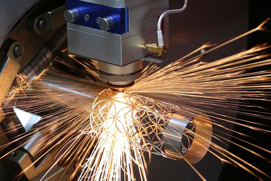
The core infrastructure couples a 5‑axis fiber laser cutting head, capable of piercing 25‑mm wall material with assist‑gas pressures above 20 bar, to a full‑length pipe‑bed loading system handling diameters from 6 to 48 inches. A pre‑process metrology station maps the pipe in three dimensions using laser profilometry, recording the actual inside/outside geometry, seam line position, and local thickness deviations. This point cloud feeds directly into the nesting engine, not as an idealized CAD model, but as a digital twin of the specific joint. From that moment, the sequence becomes deterministic. The machine controller retrieves the electronic BOM for the spool series, processes the part list through the nesting solver, and drives the cutting head along an optimized toolpath that simultaneously performs longitudinal seam tracking, bevel correction, and dynamic focus adjustment. Because the system handles lifting, rotation, and scrap ejection in a single clamped setup, total part‑type changeover drops below 90 seconds. This uninterrupted workflow sets the table for the real economic differentiator: the software algorithms that govern how the laser traverses the pipe surface.
3. Advanced Nesting Algorithms and Common‑Line Cutting Strategy
3.1 Algorithmic Nesting for Variable Part Geometries
The nesting engine does not merely pack 2D templates onto a pipe length. Every part contains parametric variables such as root face width, bevel angle (typically 10°‑30°), and inner‑outer offset vectors; each consumes a different projected arc length due to the helical cut path on the pipe cylinder. The solver must populate the 12‑meter pipe envelope while respecting minimum spacing rules for the clamping zone, the HAZ buffer around the seam line, and the scheduled remnant blocks. We have deployed a multi‑stage hybrid heuristic that pairs a fast bin‑packing stubble‑fit algorithm with a local simulated‑annealing pass to refine the layout. In production on 16‑inch X70 pipe, this method pushed packing density from 82% (manual nesting based on fixed bevel rules) to 95.6%, squeezing an additional 1.8 usable meters of part geography from every joint. The algorithm also enforces common‑line‑compatible edge geometry, actively rotating or mirroring parts to expose long straight or monotonic curved edges that can be shared.
3.2 Common‑Line Cutting: Kerf‑Sharing and Thermal Distortion Control
Common‑line cutting is the deliberate merging of adjacent part boundaries into a single laser trajectory, so the kerf—a mere 0.15‑0.20 mm slit—is shared rather than doubled. For offshore pipe, the technique is most powerful inside the repetitive bracket and lug families that surround anode attachments and pig‑launcher coupling sections. When the nesting software detects two parts whose edge geometry aligns within a 0.1 mm tolerance over a distance exceeding 50 mm, it combines them into a common‑line pair. The laser follows one continuous path, separating both parts simultaneously. This cuts the total cutting distance by 18‑22%, directly reducing assist‑gas consumption and electrical load. More critically for quenched‑and‑tempered grades, it cuts the cumulative heat input along the parting line, curbing the risk of local hard‑zone formation that could later act as a stress riser during high‑pressure hydrotesting. In one qualification run, common‑line pairing eliminated 1,040 meters of laser travel across 200 joints, trimming 7.8 kg of steel conversion loss per joint with no detectable increase in micro‑hardness at the cut edge.
3.3 Yield Maximization Through Scrap Logic and Remnant Management
Even the most sophisticated nesting cannot dissolve the inherent scrap left at pipe ends or around unweldable zones. The difference lies in how the software catalogs and reintegrates those remnants. Every partial pipe section exceeding a configurable threshold (typically 300 mm) receives a unique remnant ID, stored in a material database alongside its scanned geometry, alloy batch, and wall thickness. When the next production order for compatible material is queued, the nesting solver automatically pulls suitable remnants into first‑position priority, layering new parts onto them before touching prime pipe. Over a six‑month campaign on 24‑inch X70 gas export line pipe, dynamic remnant reuse added 4.6 percentage points of aggregate yield on top of the gains from common‑line nesting, pushing the aggregate material utilization from a baseline of 90.1% to 97.3%. In procurement terms, every 1,000 tonnes of ordered pipe generates 97.3 tonnes of usable product, moving the scrap‑to‑product ratio into a territory that directly impacts the long‑term supply agreements governed by ASME B31.8 and DNV‑ST‑F101 traceability requirements.
4. Field Validation: Yield Data from a 200‑Joint Production Run
During a North Sea tie‑back project involving 16‑inch × 25 mm wall X70 pipe with external 3LPE coating, the automated cell processed 200 joints supporting three distinct spool configurations. Each joint carried a mix of plain square‑cut ends, 22° single‑V bevels, and complex cutouts for subsea valve skid attachments. The nesting engine applied common‑line strategies across 68% of the part boundaries for the skid bracket family, while the remnant manager pulled 14 qualifying stubs from a previous riser‑hang‑off job. The measured yield was 97.3% (usable part weight vs. total pipe weight), against a baseline of 90.1% achieved with fixed‑length manual nesting on the same pipe batch. Total cycle time per joint averaged 47 minutes, including metrology, and the as‑cut bevel face roughness held below Ra 12.5 µm, meeting the direct welding acceptance criteria without a finishing pass.
Frequently Asked Procurement Questions
Q: How does common‑line cutting affect downstream weld seam integrity for high‑pressure gas pipelines?
A: The shared‑kerf technique reduces total heat input along the separation line, limiting the extent of the heat‑affected zone. Metallographic cross‑sections taken from production samples on X70 pipe with 0.15 mm kerf show no transformation‑hardened zones exceeding 0.3 mm depth, and no increase in micro‑hardness that would require post‑cut tempering. The resulting cut edge is directly weld‑ready under PQR protocols referencing ISO 15614‑1.
Q: What yield improvement should an operator expect when moving from fixed‑length manual nesting to dynamic algorithm‑based processing?
A: Based on documented runs with pipe diameters 12‑24 inches, the baseline manual yield of 88‑91% rises to 95‑97% when combining dynamic nesting with common‑line cutting and active remnant recycling. The specific gain depends on part mix complexity; the largest jumps occur when the BOM contains families of geometrically similar parts that the solver can pack into dense, shared‑edge clusters.
Q: Can the remnant tracking system interface with existing pipe‑stock ERP software to maintain EN 10204 3.1/3.2 traceability?
A: Yes. The remnant database stores the original pipe heat number, mill certificate reference, and full dimensional scan. It exports a structured XML/JSON stream that maps directly to the procurement fields of SAP/Oracle‑based material management modules. This ensures every remnant used in a new joint inherits full traceability, satisfying both project specification and regulatory archive audits without manual intervention.


