Intelligent Welding Robot System
1.1 System Composition
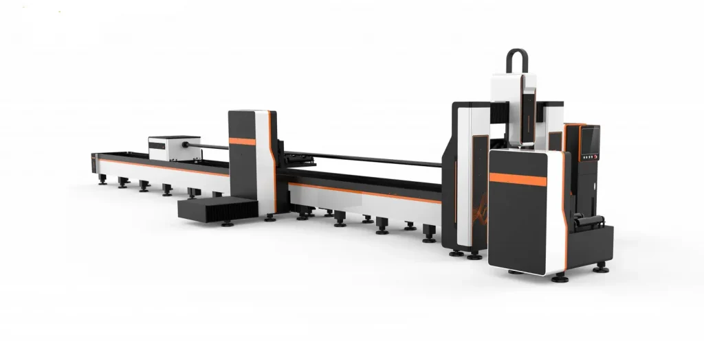
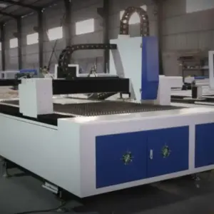
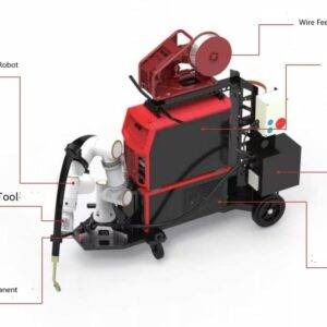
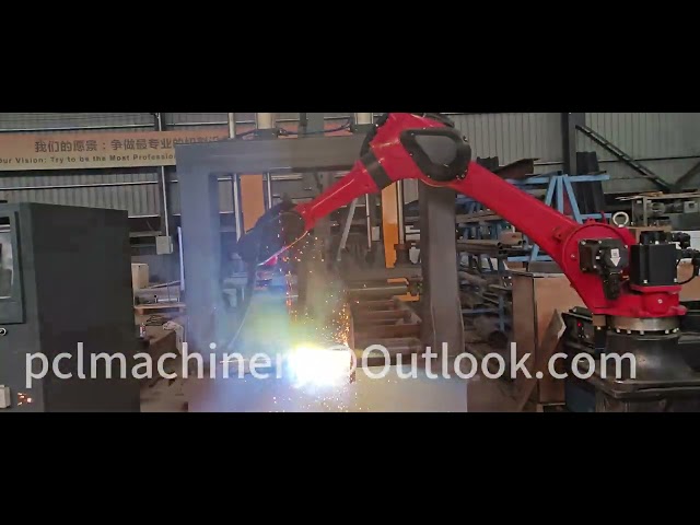
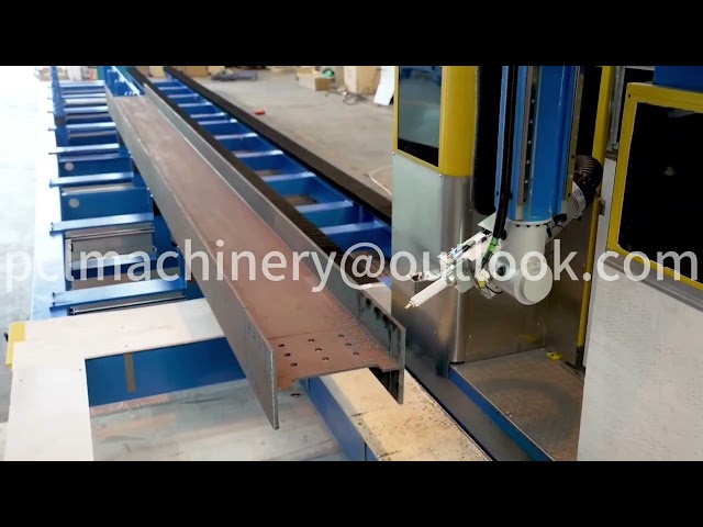
As shown in Figure 1, the hardware of the intelligent welding robot system mainly consists of the welding robot body, welding power source, wire feeder, line laser vision sensor, industrial computer (IPC), PLC, and other peripheral accessories. To expand the robot’s effective operating range and meet the welding needs of large-sized workpieces, the system can incorporate external axes and workpiece positioners.

Figure 1: Intelligent Welding Robot System for Steel Structures
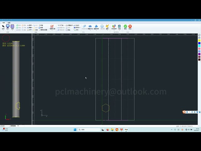
The software component mainly includes a PLC control system, offline programming software, welding process database, vision system, and information display software. The PLC control system acts as the “central nervous system” of the entire system, responsible for logical control. The offline programming software, welding process database, vision processing software, and information display software operate on the IPC. The offline programming software plans the robot’s scanning and welding paths based on the workpiece model. The welding process database provides process data. The vision system collects weld seam information, processes images and point clouds through algorithms running on the IPC, and determines the weld seam coordinates. The information display software visualizes welding progress and parameters in real time based on system feedback signals.
1.2 Welding Technical Route
In actual steel structure welding, weld formation quality is often affected by factors such as deformation, varying gaps, and misalignment. To overcome these uncertainties, it is essential to adopt weld seam scanning and layer path planning techniques to enhance the adaptability and intelligence of welding robots, achieving weld seam correction and adaptive process parameter adjustments to meet intelligent welding control requirements.
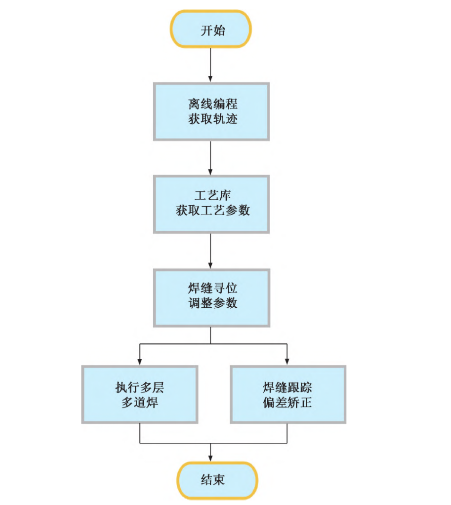
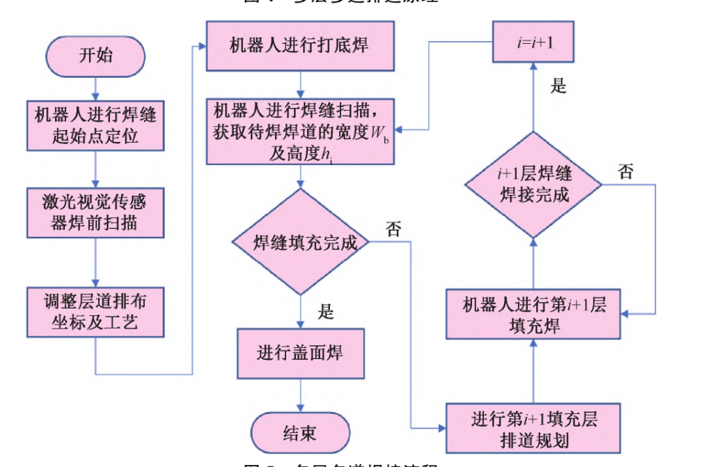
Figure 2 illustrates the intelligent welding technical route for steel structures.
The robot must complete preparatory tasks, including welding torch TCP calibration and hand-eye calibration of the line laser vision sensor with the robot. Once calibrated, if the relative position between the robot, welding torch, and vision sensor remains unchanged, recalibration is unnecessary for subsequent welding operations.
At the start of the welding task, the 3D model of the steel structure is imported into the offline programming software. Weld seam recognition extracts and edits weld seam information offline, generating seam localization and robot welding trajectories. The welding process database is referenced to determine bead arrangement and process parameters, generating the welding program. The program is then loaded into the robot controller, initiating the robot’s movement to locate the weld seam, acquire actual positional and surface morphology data, and adjust welding trajectories and process parameters. Finally, the robot executes welding while the line laser vision sensor tracks the weld seam in real time, correcting trajectory deviations and completing automatic welding.
Key Technologies for Intelligent Welding Robots in Steel Structures
With the widespread application of industrial robots and welding power sources, the robot body and welding power sources have been extensively validated through production, making them mature technologies. Therefore, the focus of intelligent welding robot system development has shifted to key areas such as automatic identification and localization of weld start points, automatic weld seam tracking, and multi-layer multi-pass bead arrangement.
1.1 Weld Seam Start Point Localization
To ensure the welding torch initiates the arc at the correct weld seam start position, seam localization is necessary. The welding robot’s vision sensing system captures and processes pre-weld images to automatically recognize weld groove features and obtain 3D spatial information. The main approaches include:
(1) Contact-Based Localization:
During seam localization, the welding wire or contact tip touches the steel plate within a limited range, generating an electrical signal to identify the start point and correct the offline-programmed position. However, this method has poor adaptability and cannot accommodate changes in the welding environment.
(2) Non-Contact Localization:
Laser vision sensors are widely used due to their simple image processing, strong anti-interference capability, and high accuracy. As shown in Figure 3, a laser vision sensor projects a line laser onto the workpiece surface, which deforms according to the workpiece shape. A camera captures the image, and using the triangulation principle, the system processes the laser image to extract features, determine weld seam coordinates, and transmit data to the welding robot for torch movement control. Researchers have extensively explored intelligent welding and welding robots. Image template matching technology is widely applied, sliding a template over the image to find matching targets. Deep convolutional neural networks (CNNs) further enhance weld seam recognition and localization accuracy, improving robustness under different conditions.

2.2 Weld Seam Tracking
During welding, heat-induced deformation inevitably causes deviations between the corrected offline trajectory and the actual welding trajectory. Sensors track weld seam position in real-time, compensating for deviations and guiding the welding torch along the actual trajectory to ensure welding precision and quality. The main tracking methods include:
(1) Arc Tracking:
Uses arc parameters as tracking signals without additional equipment. It detects current and voltage variations, recognizing and tracking the weld seam based on arc length fluctuations. This method is resistant to external light and arc interference but requires the sensor to oscillate or rotate relative to the weld seam, reducing accuracy for complex steel structure welds.
(2) Optical Sensor Tracking:
Captures weld seam images for real-time tracking. Optical sensors provide high accuracy and versatility without direct contact. They are classified as passive (dependent on ambient light) or active (emitting structured light). Active sensors are more precise, capable of handling various welding tasks with strong anti-interference properties. Laser vision sensors are the most widely used in weld seam tracking.
Various industrial laser vision sensors have been developed to support automated welding of small-batch, multi-variety steel structures, making them a key focus in the prefabricated steel structure industry.
Multi-Layer Multi-Pass Bead Arrangement
Researchers have extensively studied multi-layer multi-pass welding, focusing on pre-weld seam scanning to determine groove parameters and fill layers using equal-height or equal-area methods. However, during welding, heat input and weld formation can cause groove deformation, making pre-planned trajectories inaccurate and reducing welding quality.
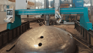
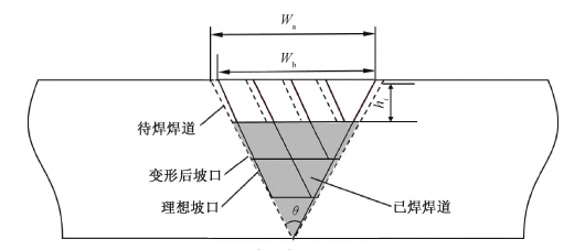
For medium-to-thick plate welding, vision-based multi-layer multi-pass planning adjusts bead placement dynamically. As shown in Figure 4, a laser vision sensor captures the actual bead distribution, extracting groove width (Wb) and layer height (hi). If deviations are within tolerance, subsequent beads follow the original plan; otherwise, the welding path is adjusted to maintain uniform filling. This method mitigates groove misalignment, workpiece deformation, and other factors affecting weld formation, ensuring optimal weld quality.
Conclusion
Intelligent welding is a crucial development direction for offshore equipment manufacturing, particularly in large-scale steel structure construction. The application of intelligent welding robots is an inevitable trend. Key technologies such as weld seam localization, seam tracking, and multi-layer multi-pass planning require further targeted research and innovation to achieve intelligent welding, ensure weld quality, and advance the offshore equipment industry. Intelligent welding robots provide reliable and efficient welding solutions for offshore construction